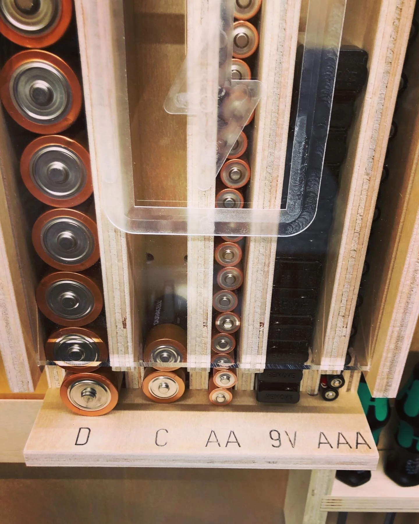
CNC

Battery Dispenser Designed in Fusion 360

Where to begin…

So far I’ve been using Adobe Illustrator to design and create the .svg files to use on the Shaper Origin. But one thing that has been a problem for me is designing projects in Illustrator that use mortise and tenons with dogbones because the thickness of the plywood affects how things fit together. This is obviously where Fusion 360 and parametric modeling shine so I really want to get better at 3D modelling.

I would also love to design something that I can cut out and it just fits together with minimal fasteners, tools or glue. This would also make it easier to sell a product because it could be flat-packed AND the customer wouldn’t need to own and operate anything more than some basic tools.

I started by watching a TON of YouTube videos from Lars Christensen, who works at Autodesk. His videos were super informative and I would highly recommend them.

The first thing I focused on was setting up the parameters.

Beyond just the obvious “plywood” parameters, the key learning for me was to set up parameters that used other parameters. For instance, I wanted to set up my “dogbone” to be slightly bigger than the cutter I was using without having to hardcode the router bit or go back and change the dogbone sizes manually. Setting up a “cutter” parameter inside of the “dogbone” parameter meant that if I wanted to make this project out of 3/4” material instead of 1/2” and use a 1/8” router bit I only had to change two parameters, “plywood” and “cutter”, then everything updated accordingly.

The next big thing I took away from this project was using multiple sketches for one body. I was always under the impression that everything about a part (body) had to be in one sketch. In fact, you can use one sketch to create the basic shape of the body and then another sketch to do things like the cutouts, mortises, tenons and dogbones. I don’t think there is a right or wrong way to do this but I could simplify it for myself by separating out some of the complexity.

Of course, there was a lot more that I learned and all of which I’ll need more practice at. I know I over engineered the hell out of this battery dispenser but it was a great learning experience.


Building the Dispenser

Files:

Materials:

  • (x1) 1/2” plywood (450mm x 900mm)

    • I have designed these files for a material thickness of 11.95mm (this will be a tight fit)

  • (x1) 6mm cast acrylic plexiglass (7” x 12”) or (177mm x 304mm)


Cutting

  1. Engrave the labels in the top of the bottom panel

    1. I used a 60 degree bit (Bit Diameter = Engrave, Cut = Online, Depth = .005)

  2. Cut out the pockets on the sides

    1. [All remaining cuts are done with a Bit Diameter = .25”]

    2. First pass (Cut = Pocket, Depth = .25”)

    3. Second pass (Cut = Inside, Depth = .25”)

  3. Cut guide in side panels for plexiglass front

    1. There is a line on each of the side pieces that is intended to hold the plexiglass front (Cut = Online, Offset = 0”, Depth = .25”)

  4. Cut out the mortises (you can do this for one part at a time or all of the parts)

    1. First pass (Cut = Outside, Offset = .03”, Depth = .25”)

    2. Second pass (Cut = Outside, Offset = 0”, Depth = .5”)

  5. Cut out the plywood parts

    1. First pass (Cut = Outside, Offset = .03”, Depth = .25”)

    2. Second pass (Cut = Outside, Offset = .0”, Depth = .5”)

  6. Cut the plexiglass front

    1. If you purchased the linked plexiglass above, or have a piece larger then the outside dimensions, use a tablesaw to cut it down to size (7” x 12”)

    2. Cut out the finger hole

      1. First pass (Cut = Outside, Offset = .03”, Depth = .25”)

      2. Second pass (Cut = Outside, Offset = .0”, Depth = .5”)

    3. Pocket out the illustration

      1. Pocket and Inside cut (Offset = 0”, Depth = .05”)

Assembly

This is intended to be a tight fit so you will need a scrap piece of plywood and small mallet to assemble the pieces together.

  1. Install the Dividers into the Bottom piece

  2. Add the Top

  3. Align and install the tenons from the assembly to the back panel

  4. Align and install the assembly into each of the side pieces

  5. I didn’t use any glue but I did use a nail gun to add one pin to each side to make sure the sides don’t come loose.

In the end I was excited to see the 3D model come to life and I’m really happy with how tightly everything fit. I’m looking forward to the next project.

As always, I hope this helped.

Cheers,

Lee


Tools and Materials used