The BEEZLEE Blog Woodworking, Tools, Design Lee Bizek 1/1/21 Woodworking, Tools, Design Lee Bizek 1/1/21 Mobile Cart for Festool / Shaper Systainer Read More Innovation, Technology, Tools, Woodworking Lee Bizek 5/25/20 Innovation, Technology, Tools, Woodworking Lee Bizek 5/25/20 Let There Be Light! Read More Design, Woodworking Lee Bizek 5/21/20 Design, Woodworking Lee Bizek 5/21/20 Battery Dispenser Designed in Fusion 360 Read More
Woodworking, Tools, Design Lee Bizek 1/1/21 Woodworking, Tools, Design Lee Bizek 1/1/21 Mobile Cart for Festool / Shaper Systainer Read More
Innovation, Technology, Tools, Woodworking Lee Bizek 5/25/20 Innovation, Technology, Tools, Woodworking Lee Bizek 5/25/20 Let There Be Light! Read More
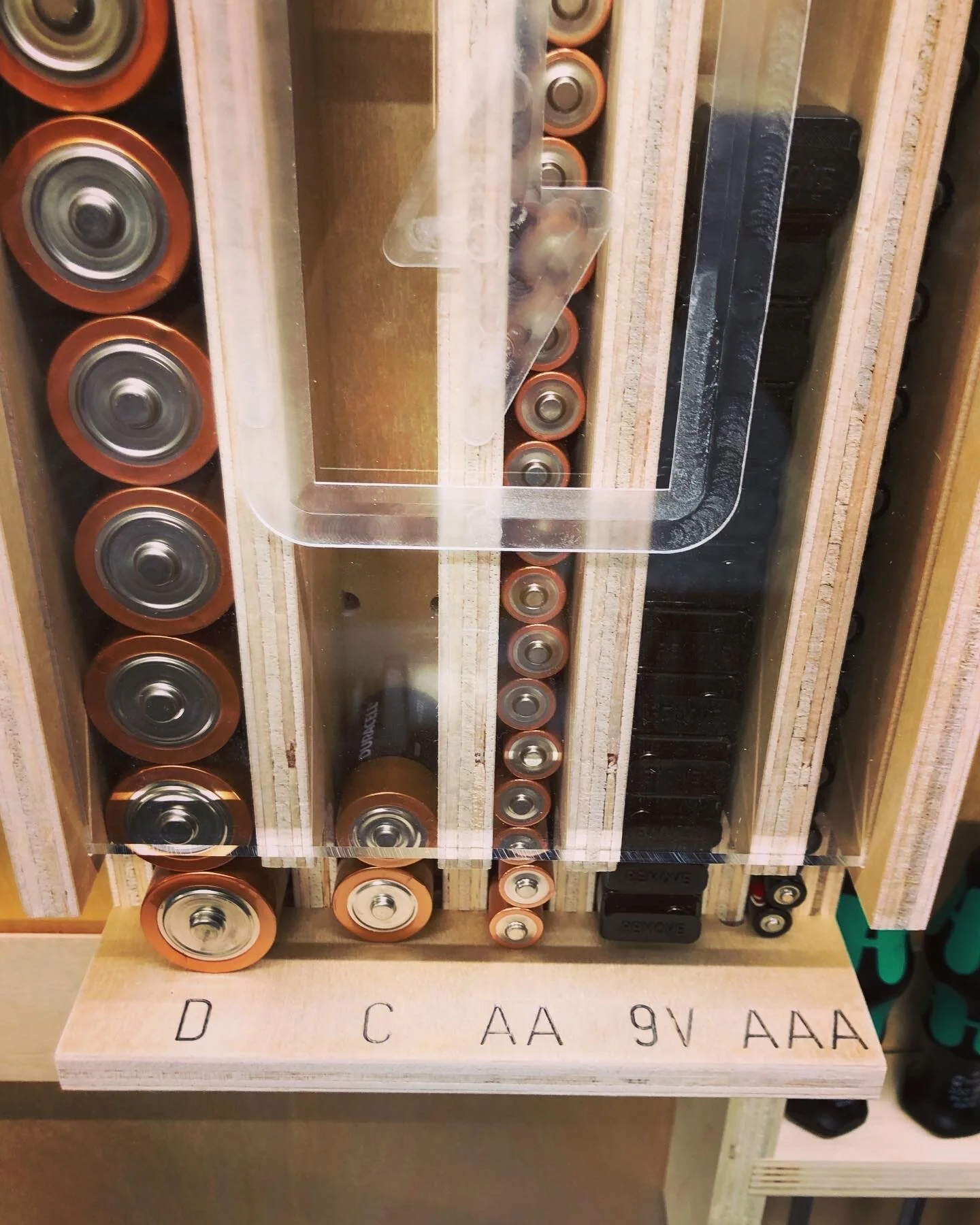
Design, Woodworking Lee Bizek 5/21/20 Design, Woodworking Lee Bizek 5/21/20 Battery Dispenser Designed in Fusion 360 Read More