The BEEZLEE Blog Tools, Design Lee Bizek 12/14/19 Tools, Design Lee Bizek 12/14/19 Corner Jigs made with Shaper Origin Read More Tools Lee Bizek 11/9/18 Tools Lee Bizek 11/9/18 Horizontal Support for Shaper Origin "Ultimate" Vertical Workstation Read More Tools Lee Bizek 7/6/18 Tools Lee Bizek 7/6/18 "Ultimate" Vertical Workstation for Shaper Origin Read More
Tools, Design Lee Bizek 12/14/19 Tools, Design Lee Bizek 12/14/19 Corner Jigs made with Shaper Origin Read More
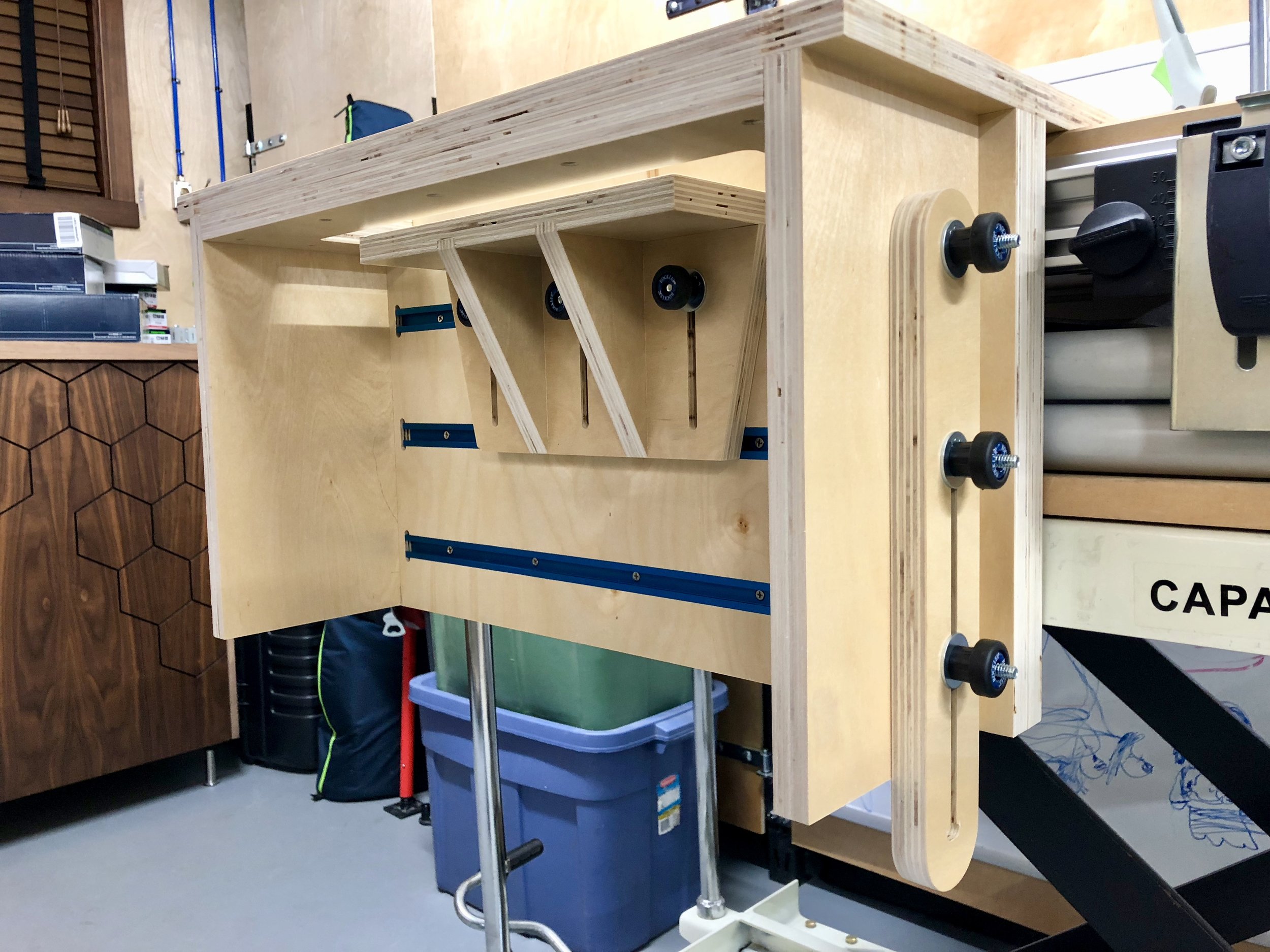
Tools Lee Bizek 11/9/18 Tools Lee Bizek 11/9/18 Horizontal Support for Shaper Origin "Ultimate" Vertical Workstation Read More
Tools Lee Bizek 7/6/18 Tools Lee Bizek 7/6/18 "Ultimate" Vertical Workstation for Shaper Origin Read More