

Occasionally I do custom jobs, like built-ins, at client’s homes. There is a lot of work that goes into packing up almost the entire shop, putting it into the back of the truck, unpacking onsite and then setting up in a small, temporary space like a garage or outside. I’ve said to myself on a number of occasions that it would be great to have a few mobile carts that I could use to stack and move around all of my Festool and Shaper tools. But at $100 a pop for the Festool mobile cart it just seems a bit excessive. Since it’s just a platform that locks to the bottom of the box with some wheels I thought I would give it a go at creating my own. If you follow the steps below you can build one yourself for about $40 and get 6 carts out of one sheet of 3/4” plywood!
Design and Rendering
I started out in SketchUp by imported a systainer from the 3D Warehouse created by Brice Burrell. I used this to cut away the shape of the systainer, mocked up some handles and did some other minor tweaking to give the cutout a bit of an offset.
Festool Systainer model by Brice Burrell used to design model of cart
I had to play around with this to figure it out but ultimately I needed to get a 2D image out of SketchUp and an .svg file into the Shaper Origin. Here’s the way I did it.
In SketchUp, hide everything except the shape you’re trying to get into Shaper.
Then go to Camera > Standard Views > Top (Cmd+1)
Turn off perspective Camera > Perspective (uncheck)
2D Top view ready for Export
Now the image is ready for export.
Click File > Export > 2D Graphic
I used .eps as the file type
Then I opened the .eps file in Adobe Illustrator, made changes to the colors for the Shaper Origin and then saved the .svg file to upload to my ShaperHub cloud storage
After cutting out the first prototype I came back to Illustrator to make modifications for tabs to hold down the systainer, make the handles smaller and minor tweaks to accommodate the shape of the new Systainer3 which is slightly different.
Making edits to the file in Illustrator and saving .svg file
From Virtual to Physical
Materials Needed:
(x1) 18mm (3/4”) plywood 1195mm x 387mm (47” x 15-1/4”)
(x1) 12mm (1/2”) plywood 125mm x 77mm (5” x 3”) for all tabs
(x4) Casters - https://amzn.to/3rKpVxQ
(x2) 1/4-20 Threaded Insert - https://amzn.to/3506Gq3
(x2) 1” Knob with 1/4-20, 1” threaded stud - https://amzn.to/3n9918C
Glue, screws, washers
*All cuts are made with a 1/4” compression (up/down) spiral bit.
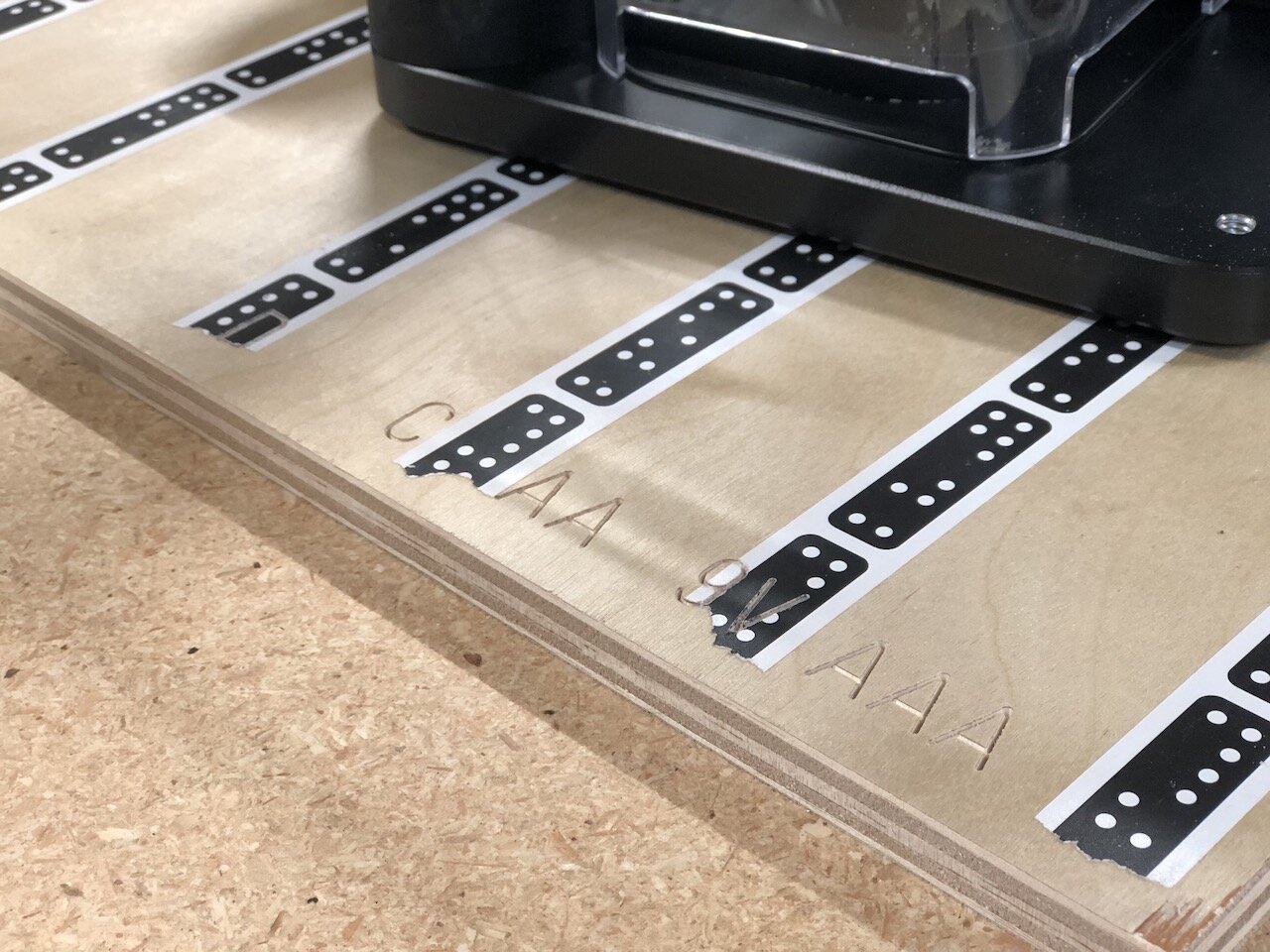
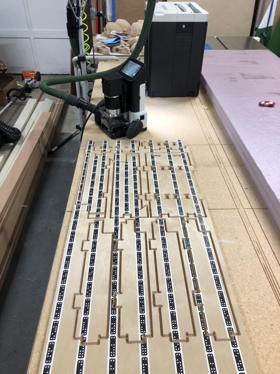
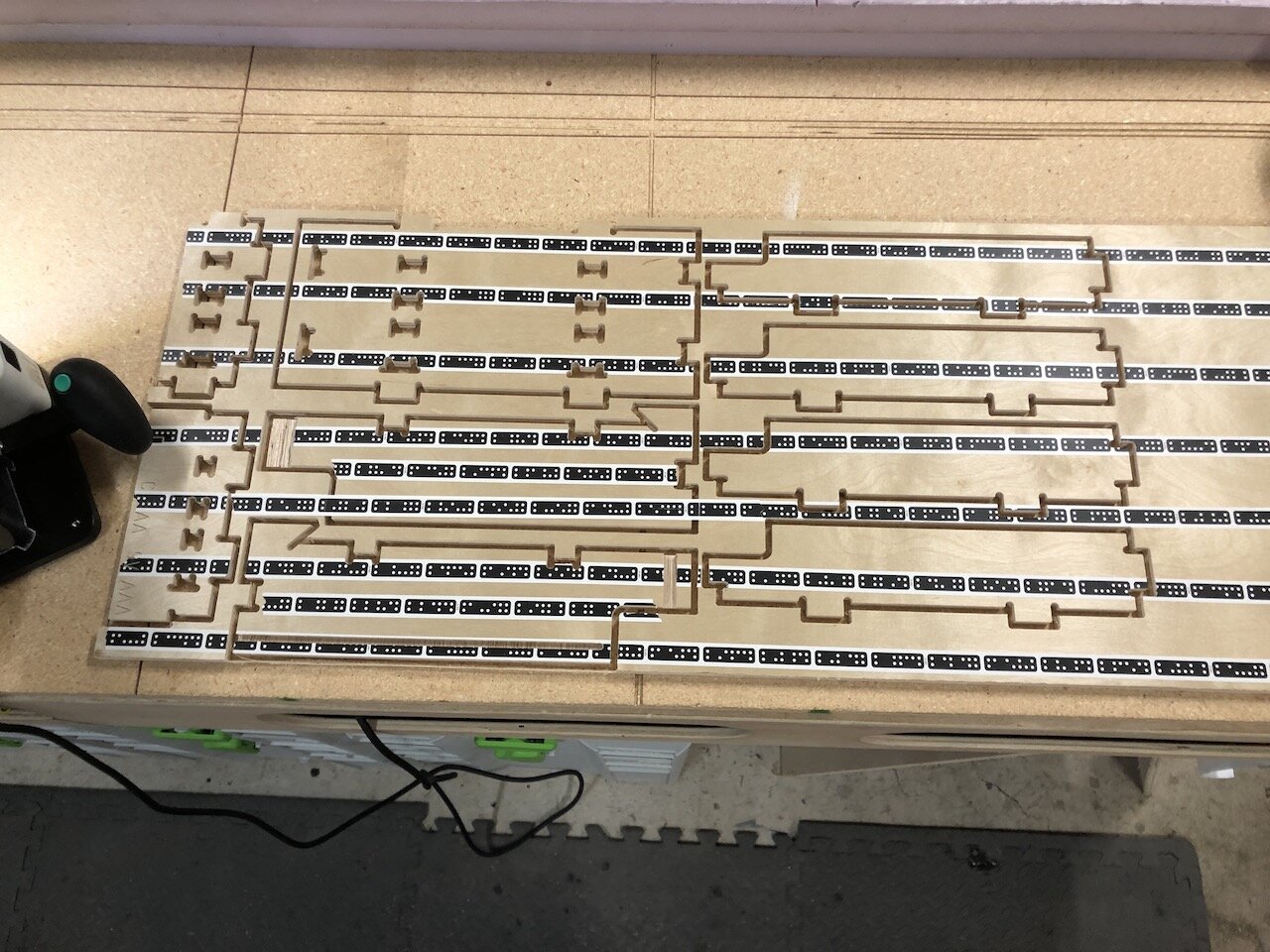
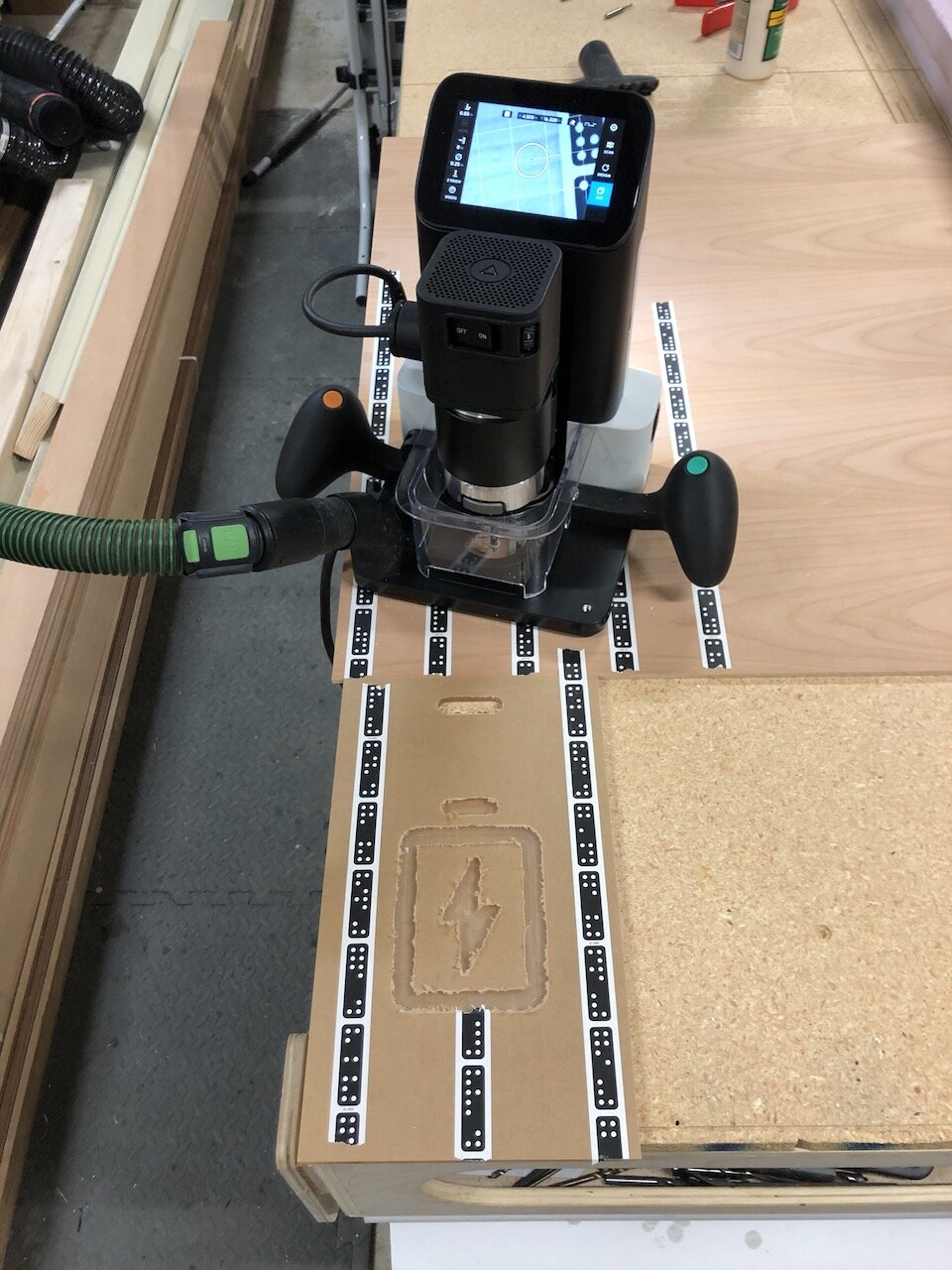
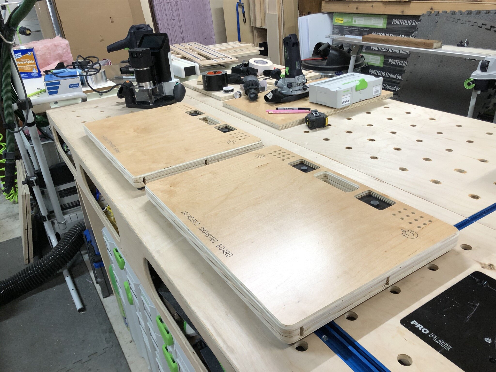
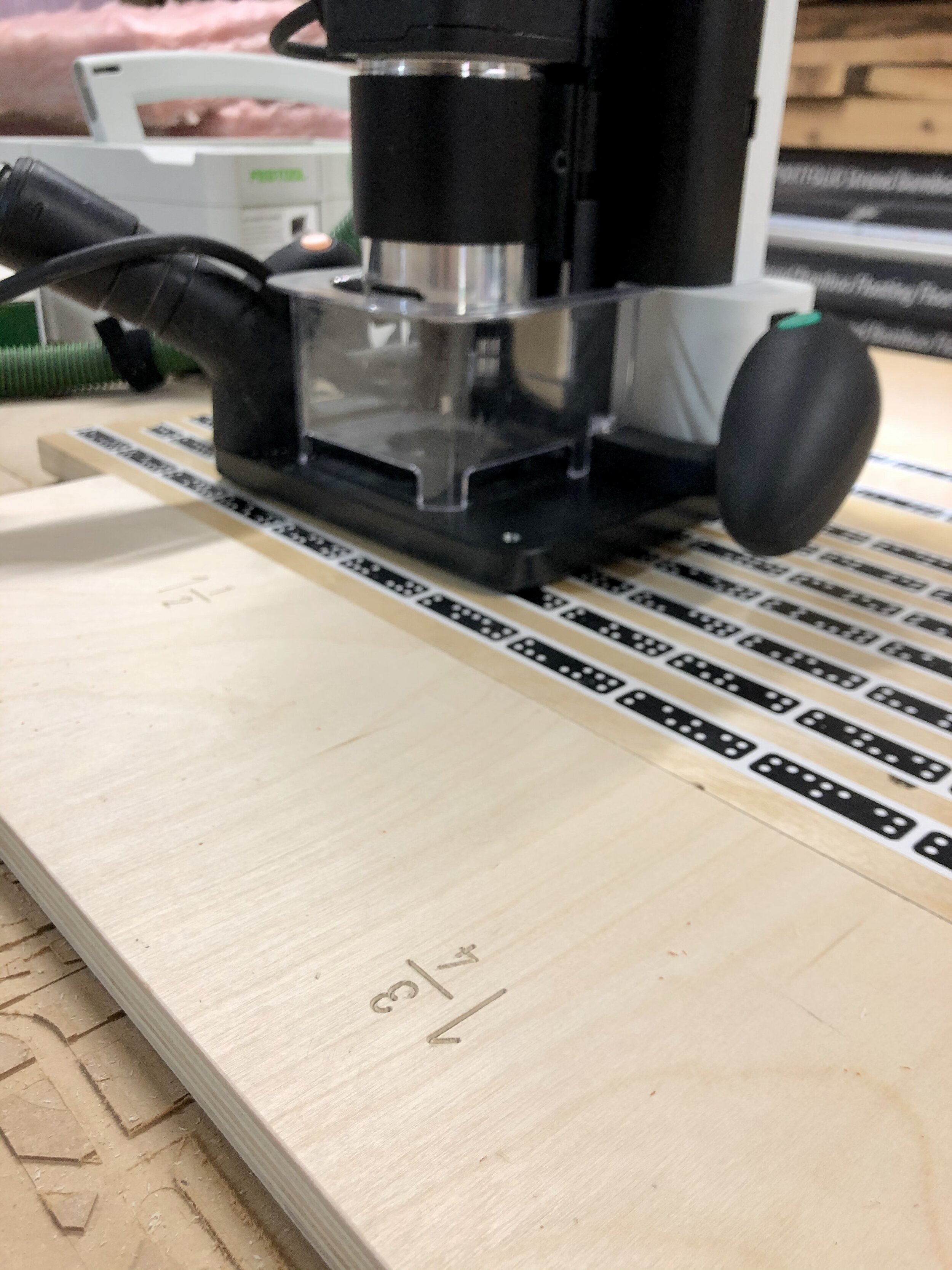
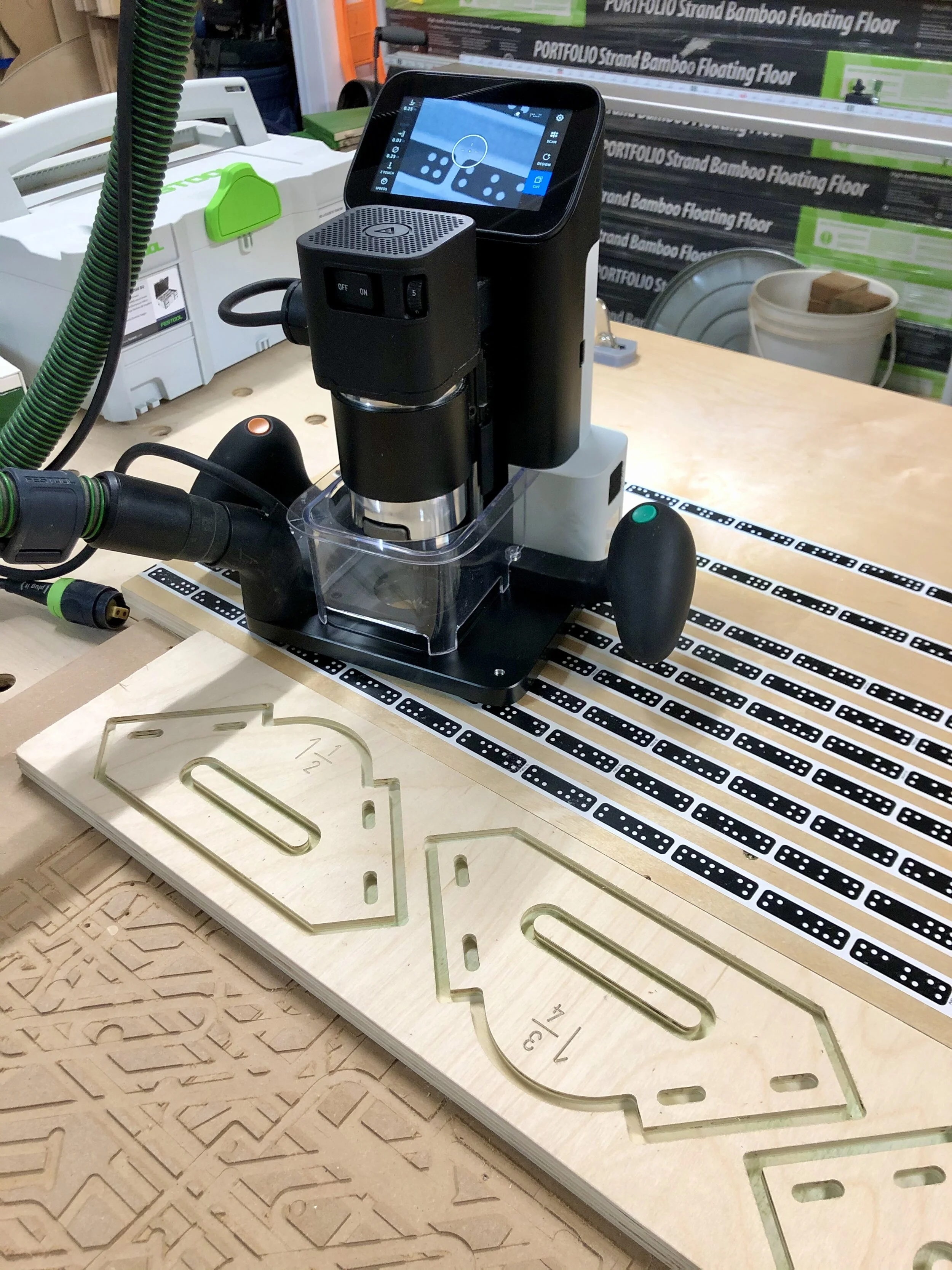
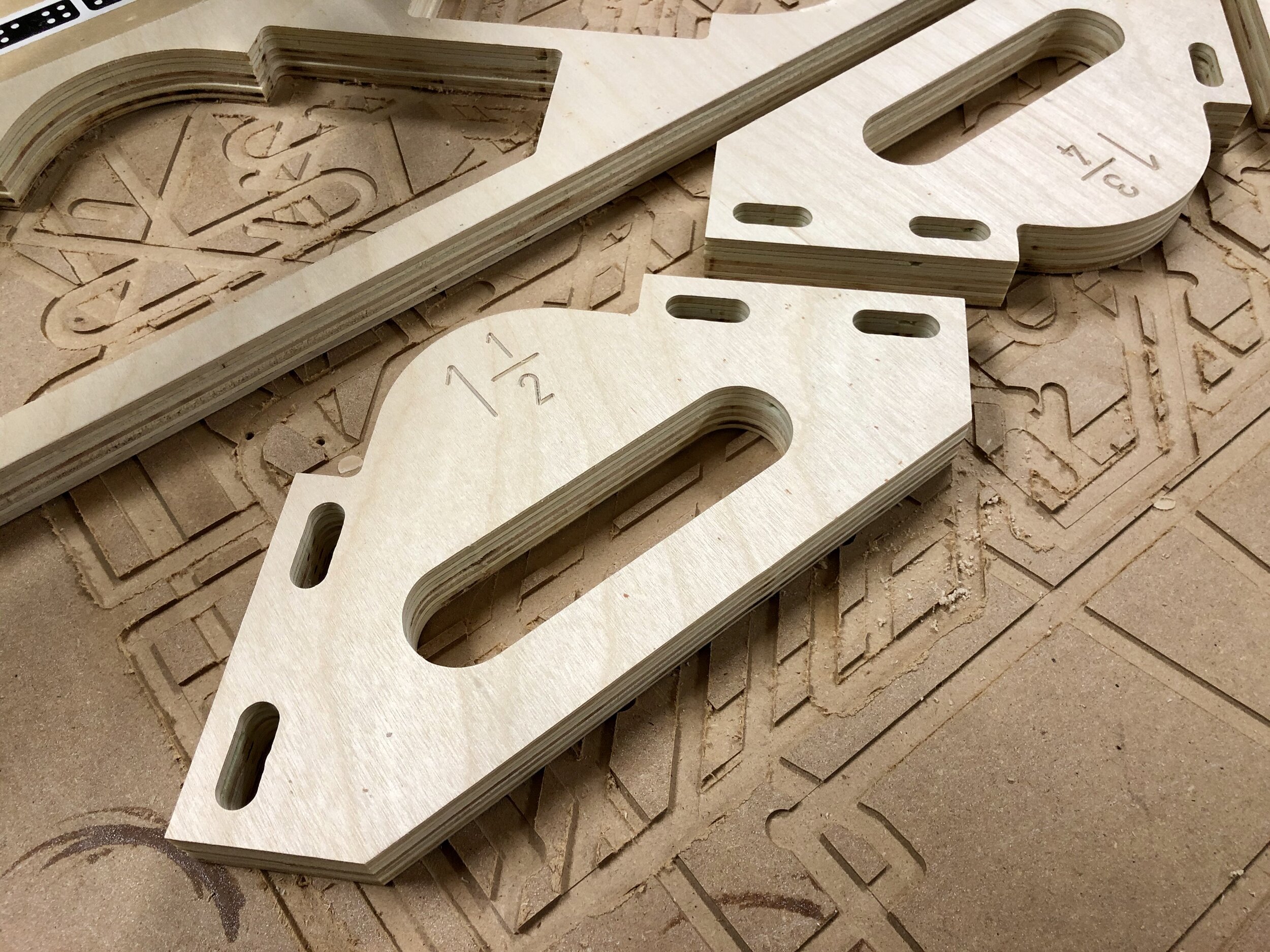
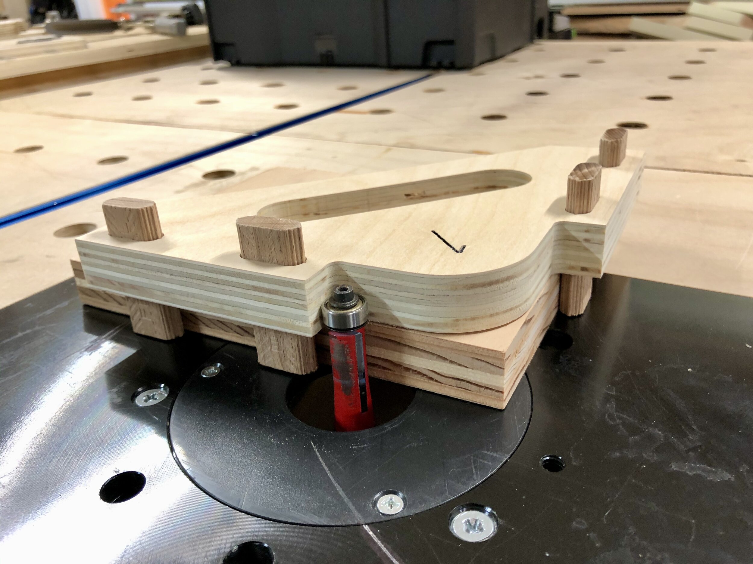
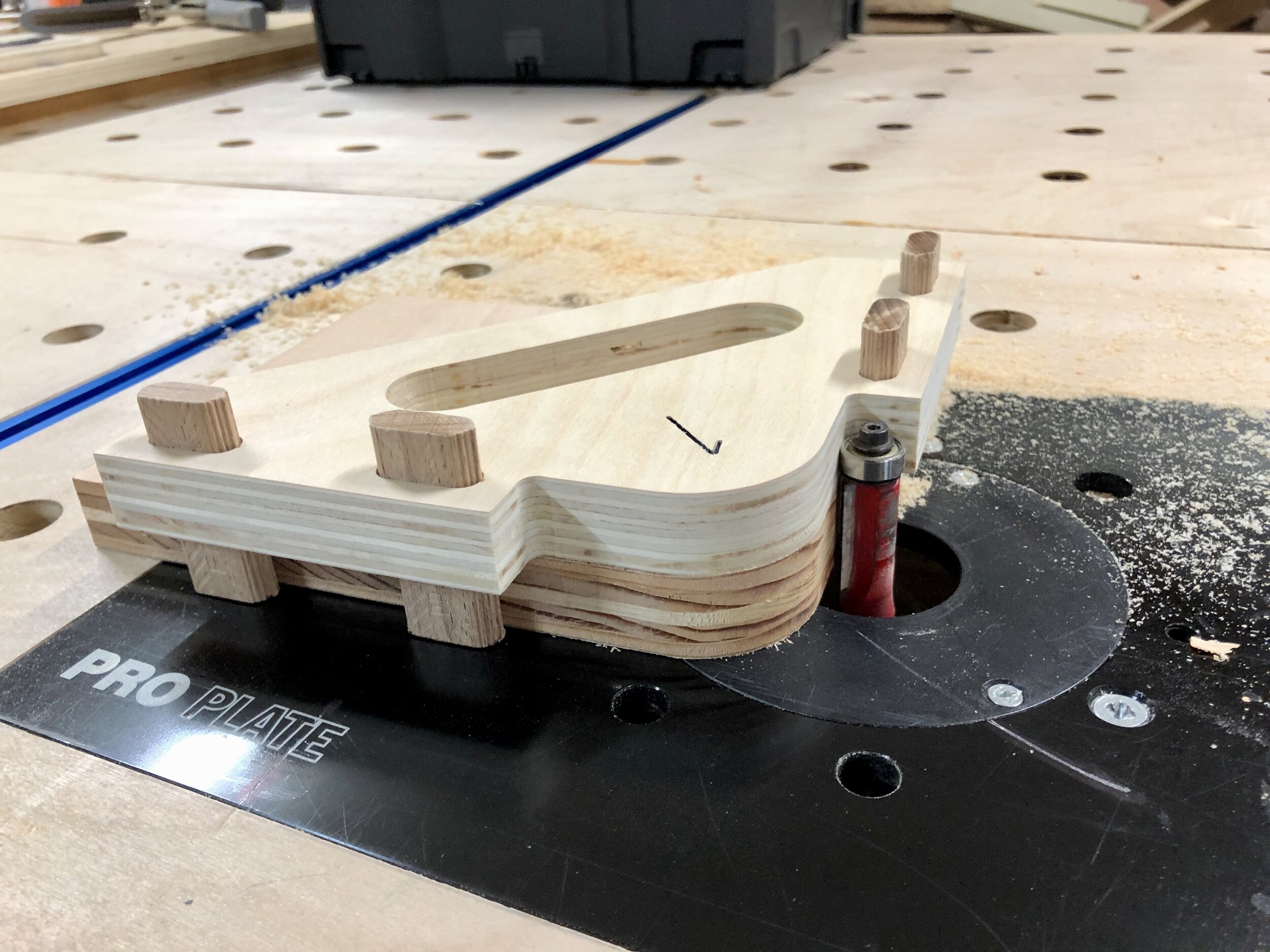
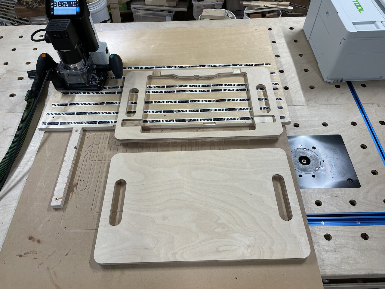
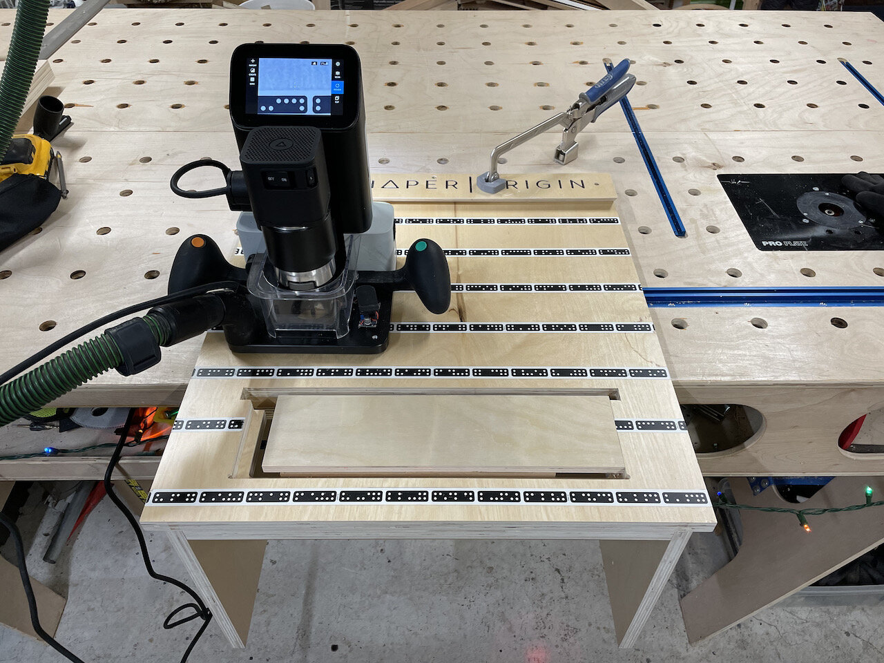
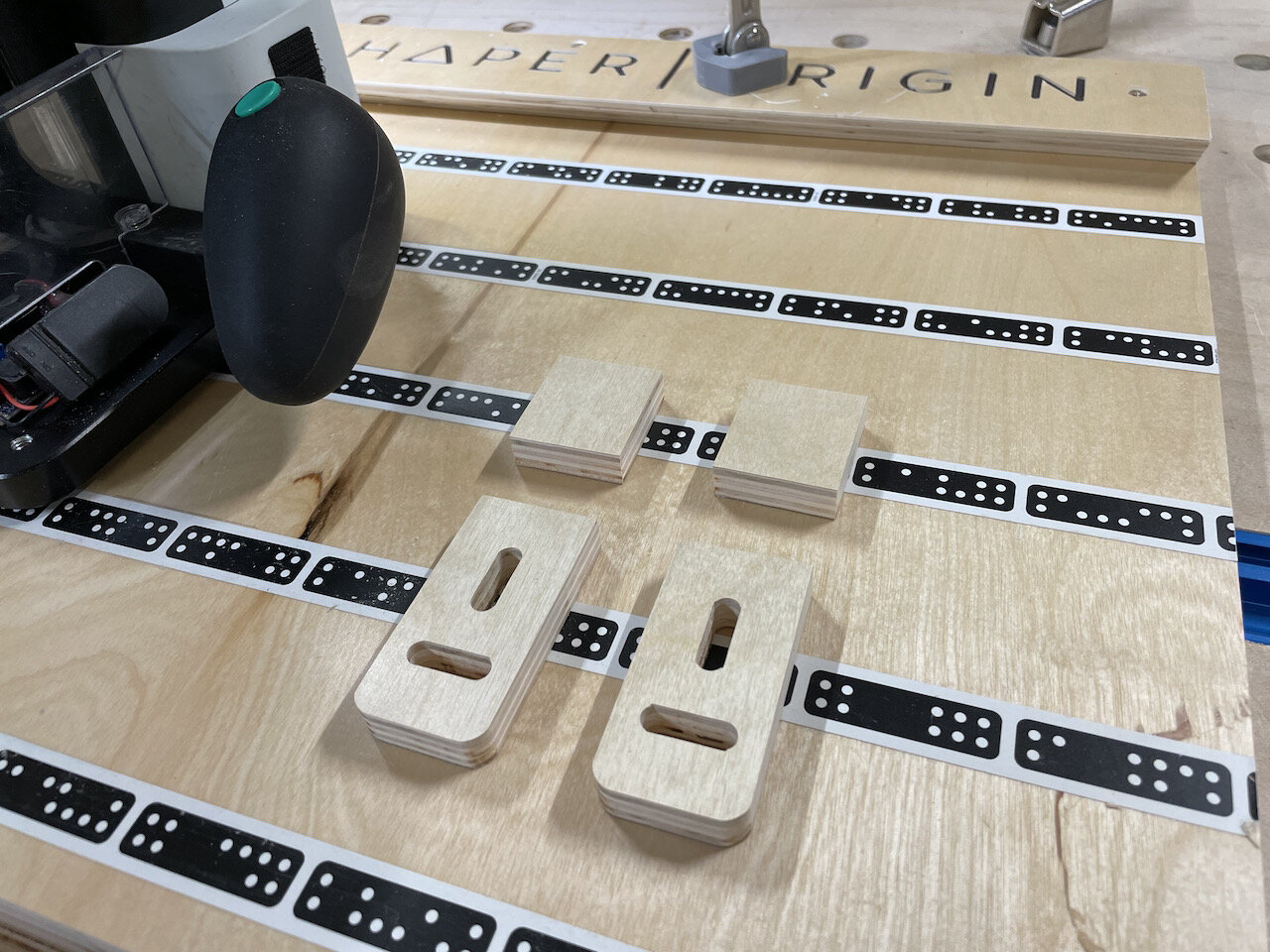
As shown in the pictures below, I am using a board with a straight edge and marker tape with another scrap piece for alignment on the left side so that I can place the image once and make repeat cuts for as many top and bottom pieces as I like. You can of course, place the image multiple times on a single sheet of plywood if you don’t prefer to use this method.
Cutting Top
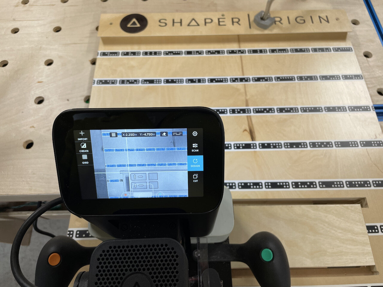
Create a grid that lines up with the board of Shaper Tape and along a stop block to the left (I used .5” grid pattern)
Secure the 3/4” plywood so that it is touching the board with tape and the stop block to the left
No additional tape is required on the work piece since the Origin will read the tape from the board all the way around the cut
Using the top, left corner of the image as the anchor, place the image down and to the right one block (.5” grid) from the corner where the stop block and tape board touch
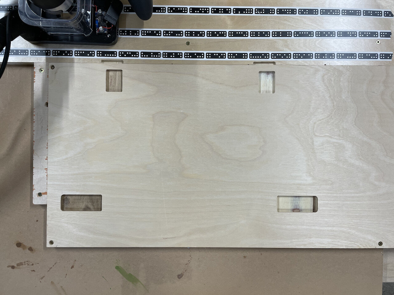
Cut pockets for hold down tabs first
Depth: .25”
Cut Type: Pocket (then Inside)
Offset: 0”
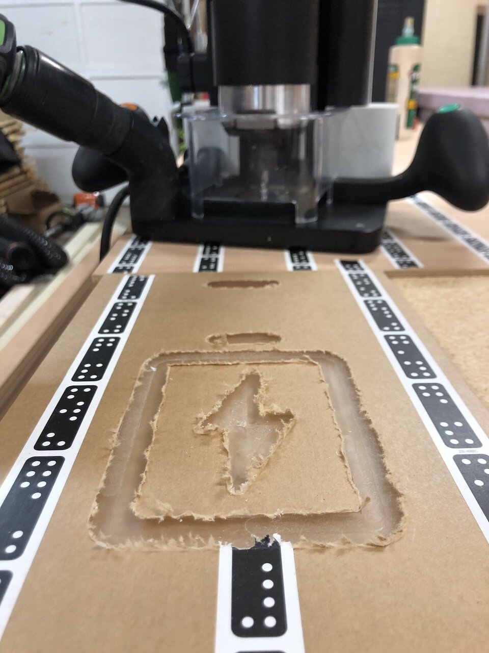
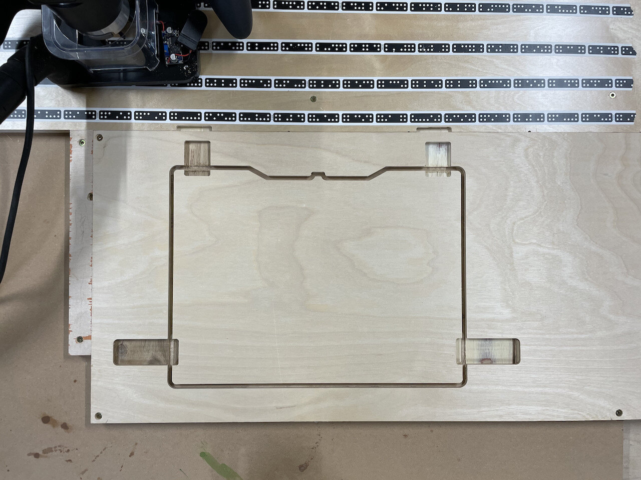
Cut out interior systainer cutout
Three passes:
Depth: 8mm; Cut Type: Outside; Offset: .01”
NOTE: Since I’m using a compression bit this depth is used to bury the “up cut” tip of the bit fully, preventing tear out.
Depth: 1/2”; Cut Type: Outside; Offset: .01”
Depth: 3/4”; Cut Type: Outside; Offset: 0”
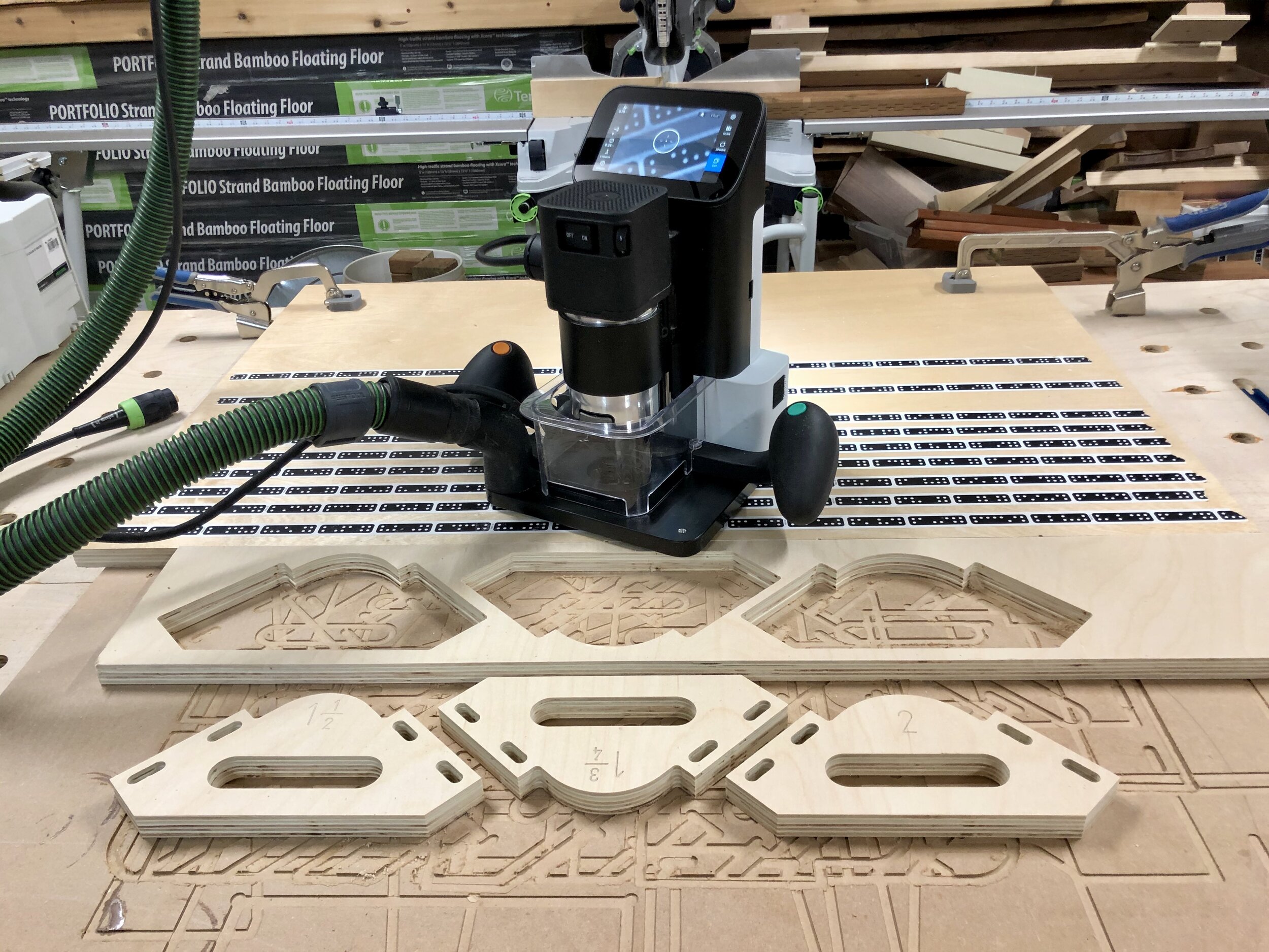
At this point make sure the systainer fits into the cutout. it should have a small amount of wiggle room to make it easier to put the systainer in and out of the cutout once the tabs are in place.
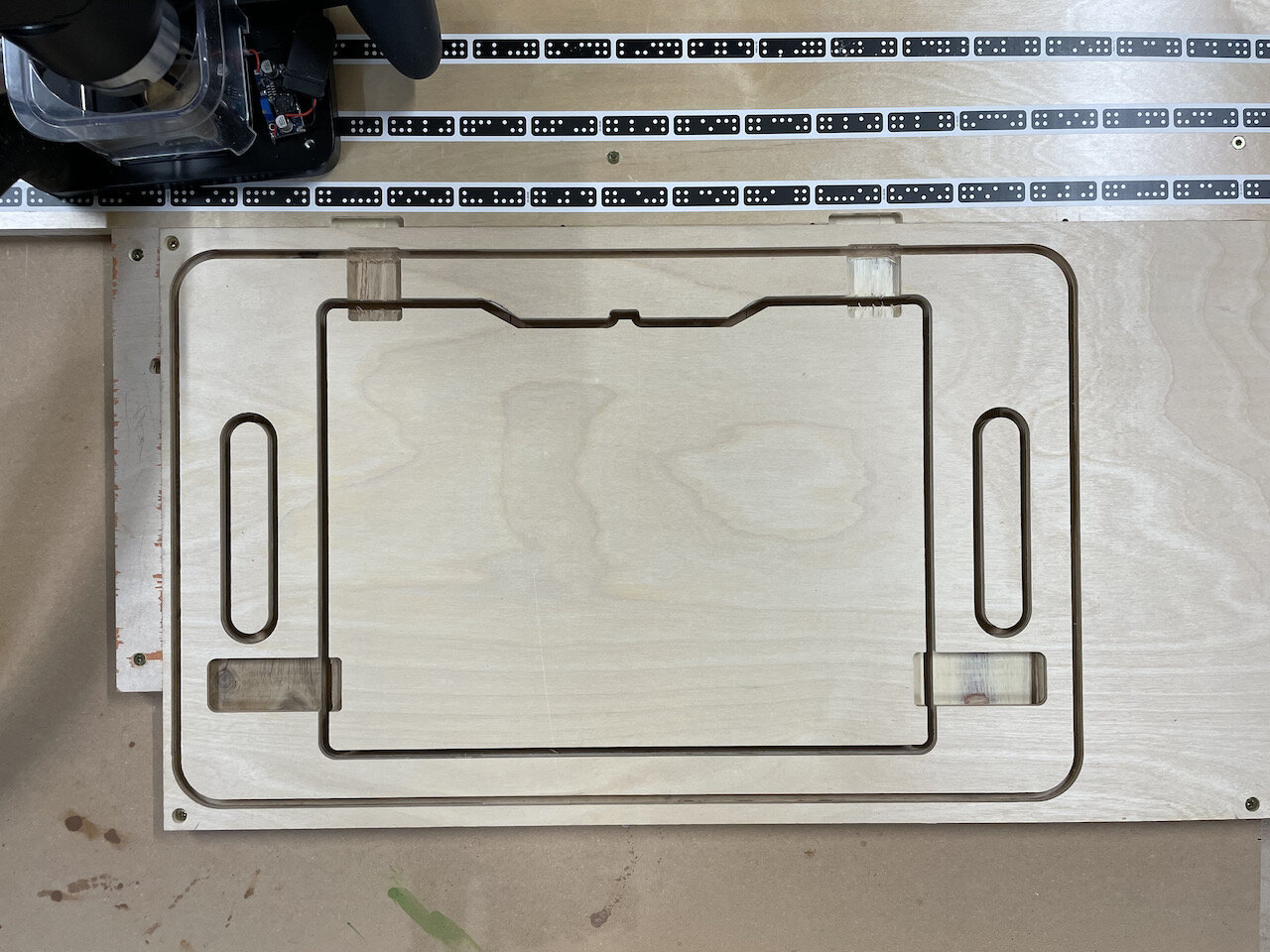
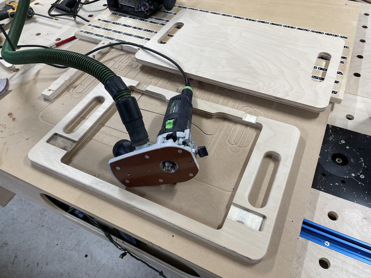
Cut out handles
Three passes:
Depth: 8mm; Cut Type: Outside; Offset: .01”
Depth: 1/2”; Cut Type: Outside; Offset: .01”
Depth: 3/4”; Cut Type: Outside; Offset: 0”
Cut out exterior
Three passes:
Depth: 8mm; Cut Type: Outside; Offset: .01”
Depth: 1/2”; Cut Type: Outside; Offset: .01”
Depth: 3/4”; Cut Type: Outside; Offset: 0”
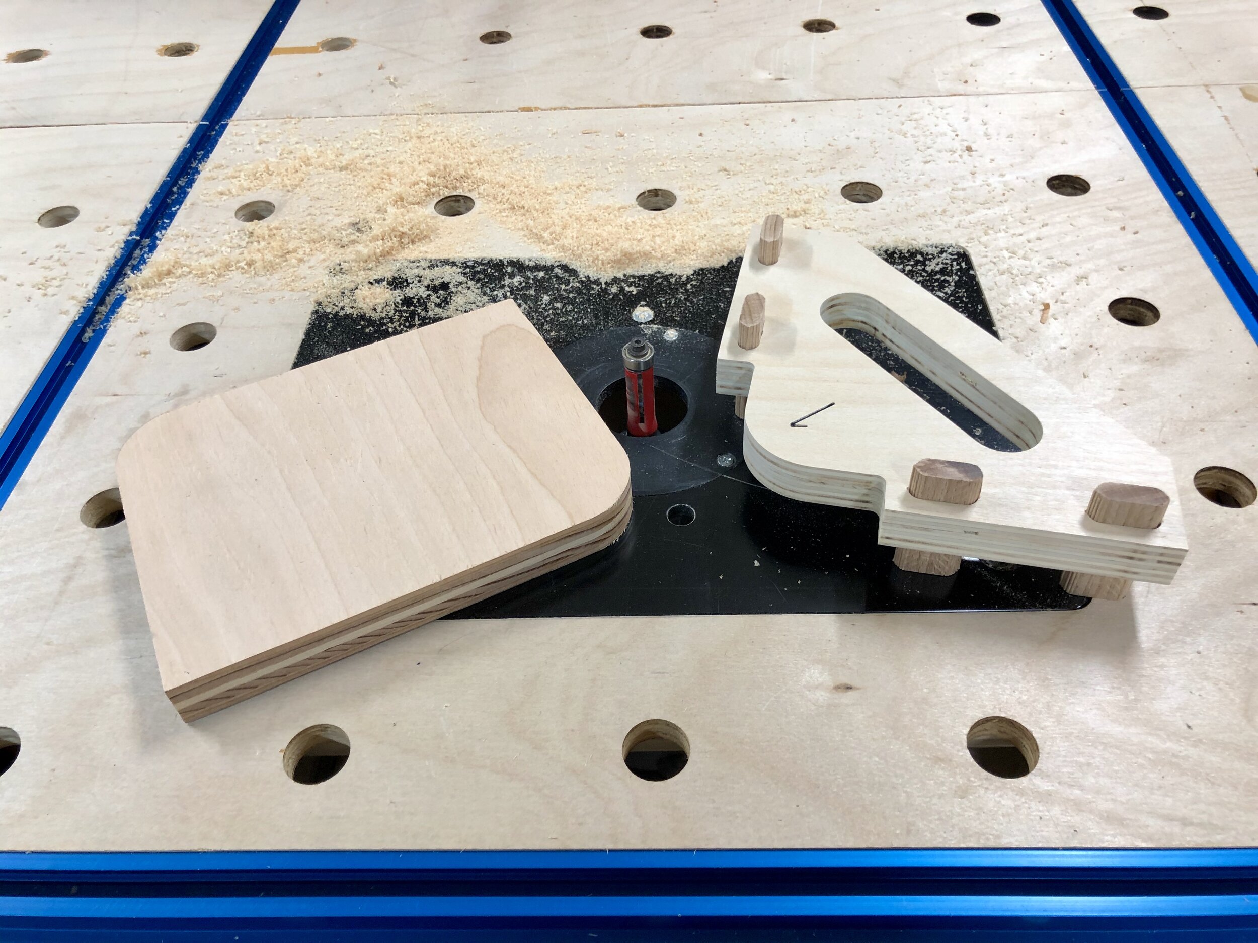
Cutting Bottom
LEAVE IMAGE AS IS. You can now simple flip the piece of plywood over to align the other side with bottom edge of tape board and stop block to cut out the bottom piece
Cut out the handles (the same as Step 7 of the Top)
Cut out exterior (the same as Step 8 of the Top)
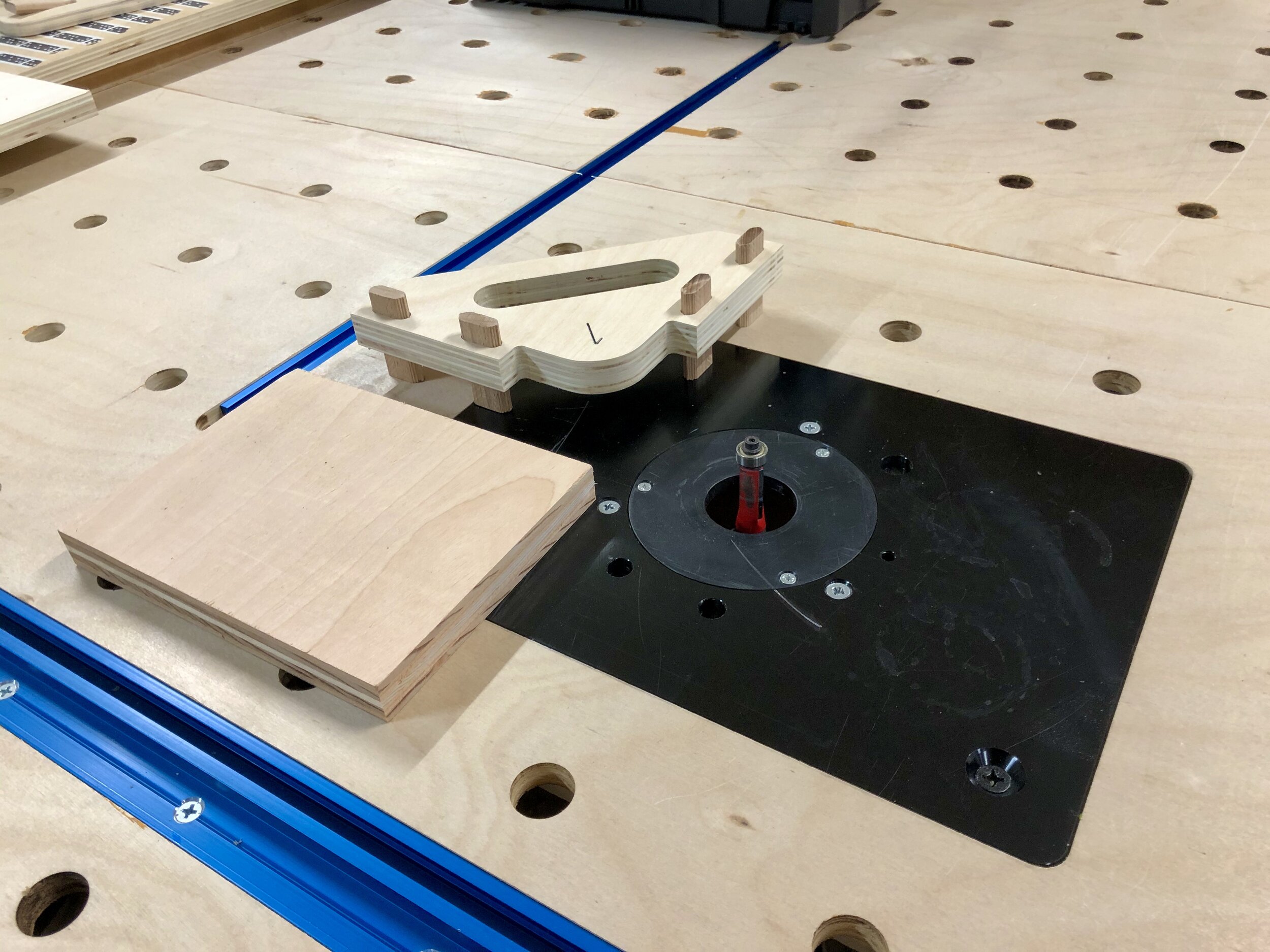
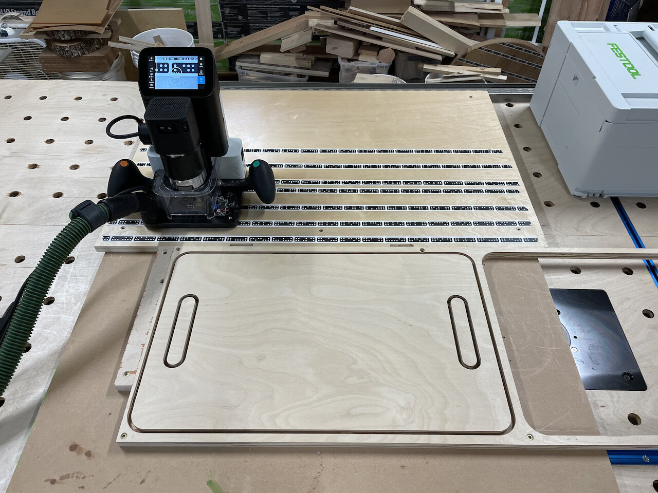
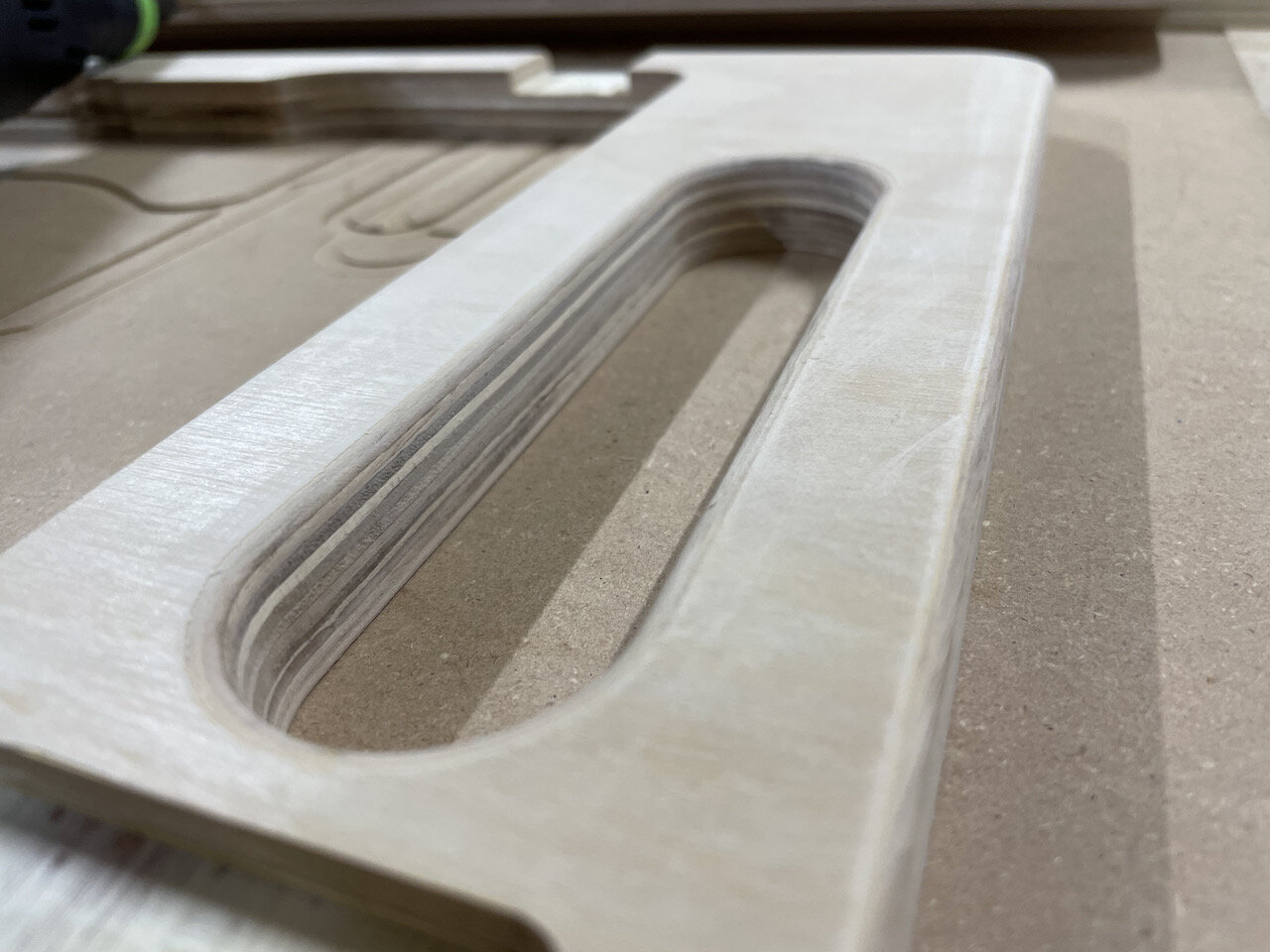
I then used a 1/8” roundover bit to soften the handles and exterior edges
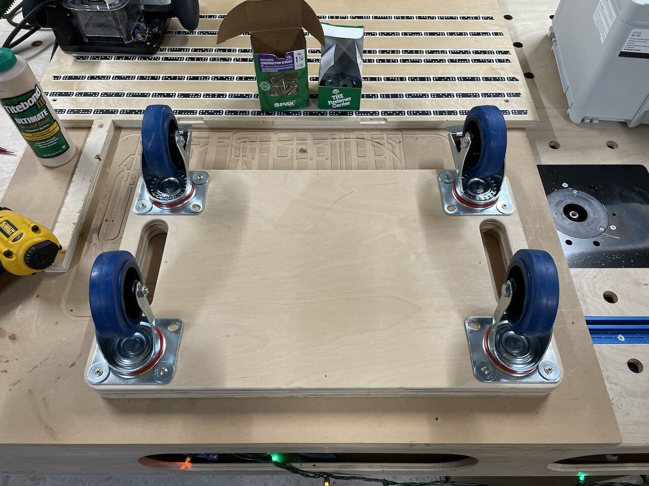
Turn the pieces over, place glue on the underside of the top piece, line up the bottom piece and use a brad nail in each corner to hold it in place
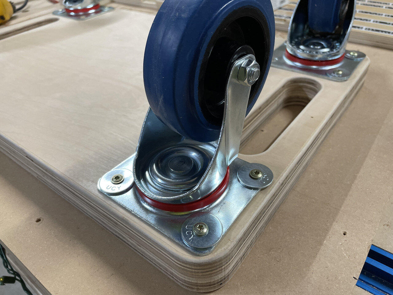
Install wheels to the base. Lockable wheels in the front.
Since I was using 1-1/4” screws I only used three of the four holes because the inner most screw would go complete through the bottom piece into the space where the systainer will sit. I also used washers since the heavy duty casters I’m using have holes that are meant for larger bolts.
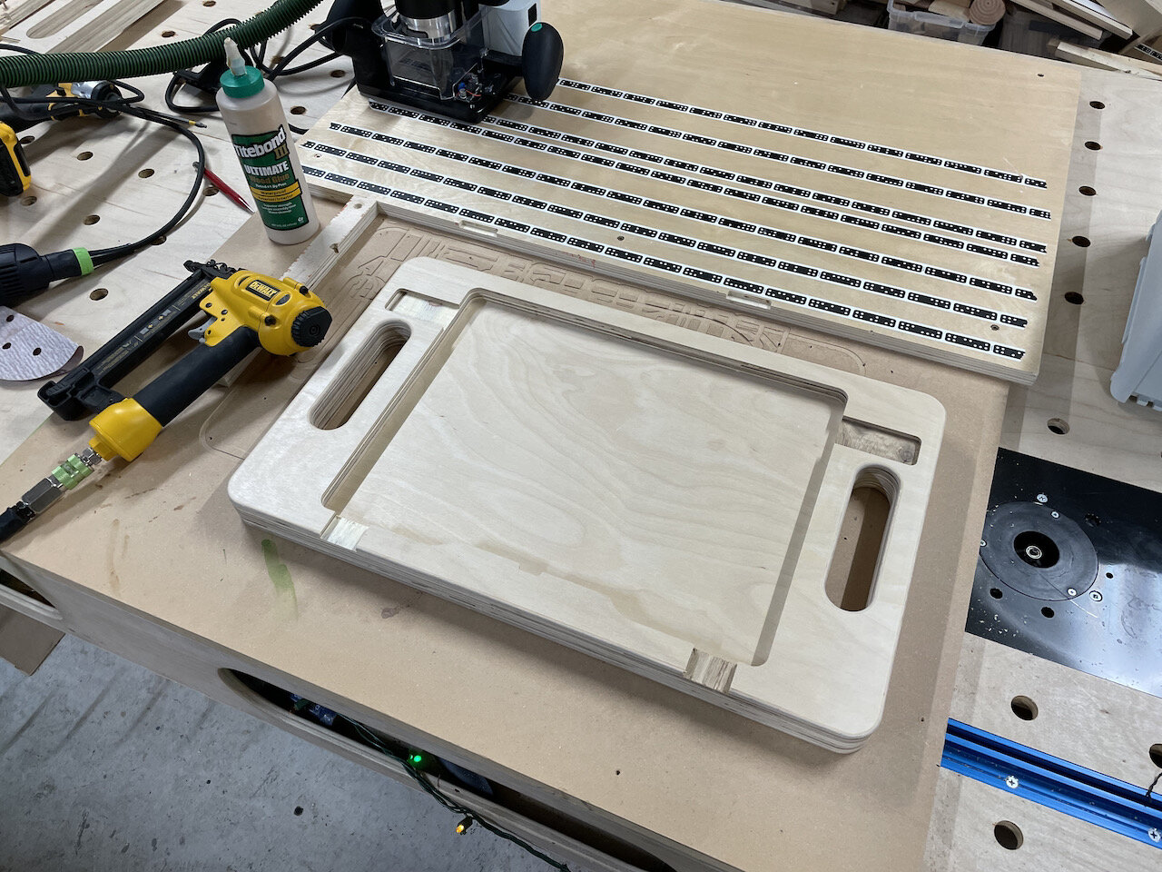
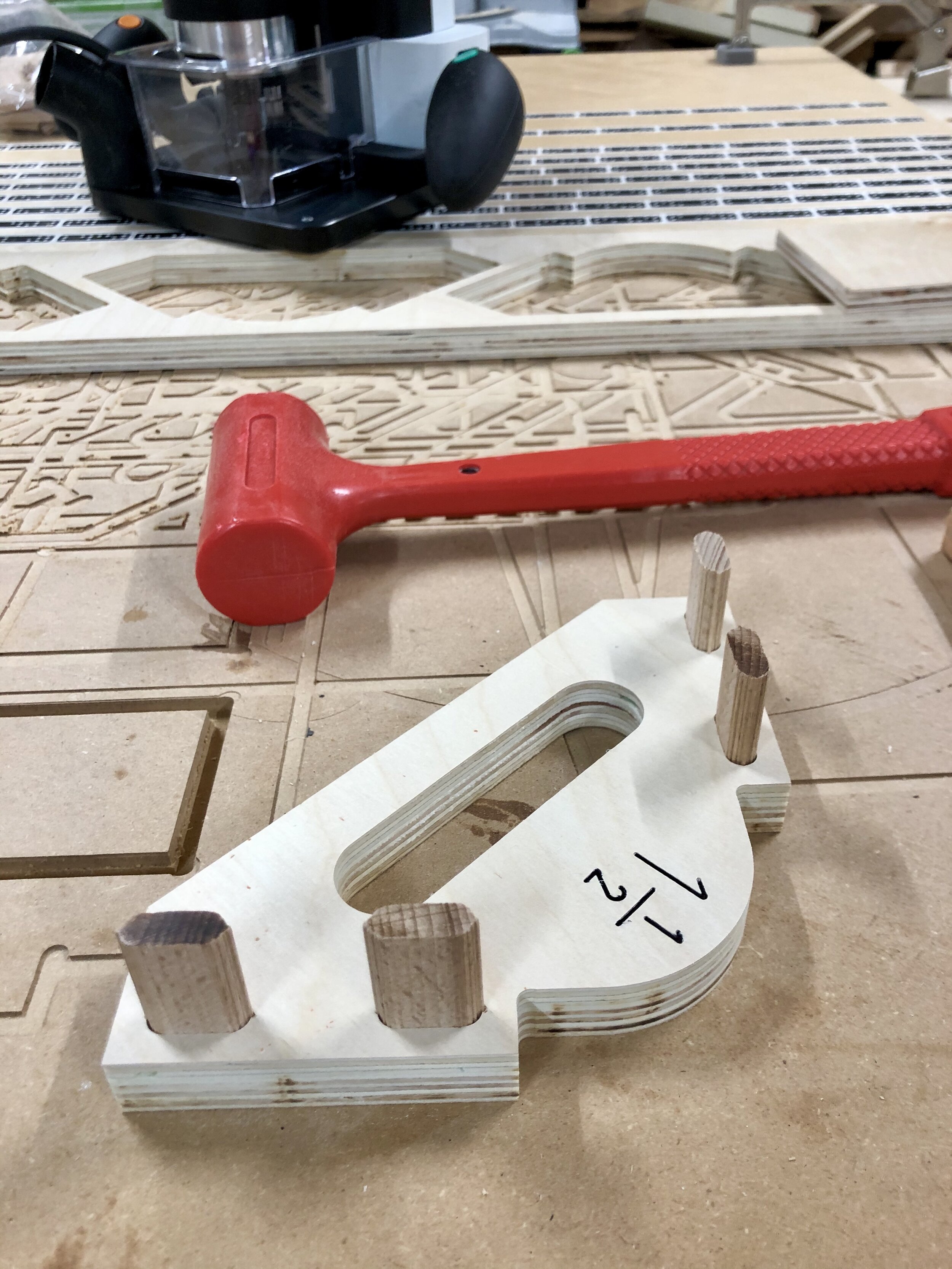
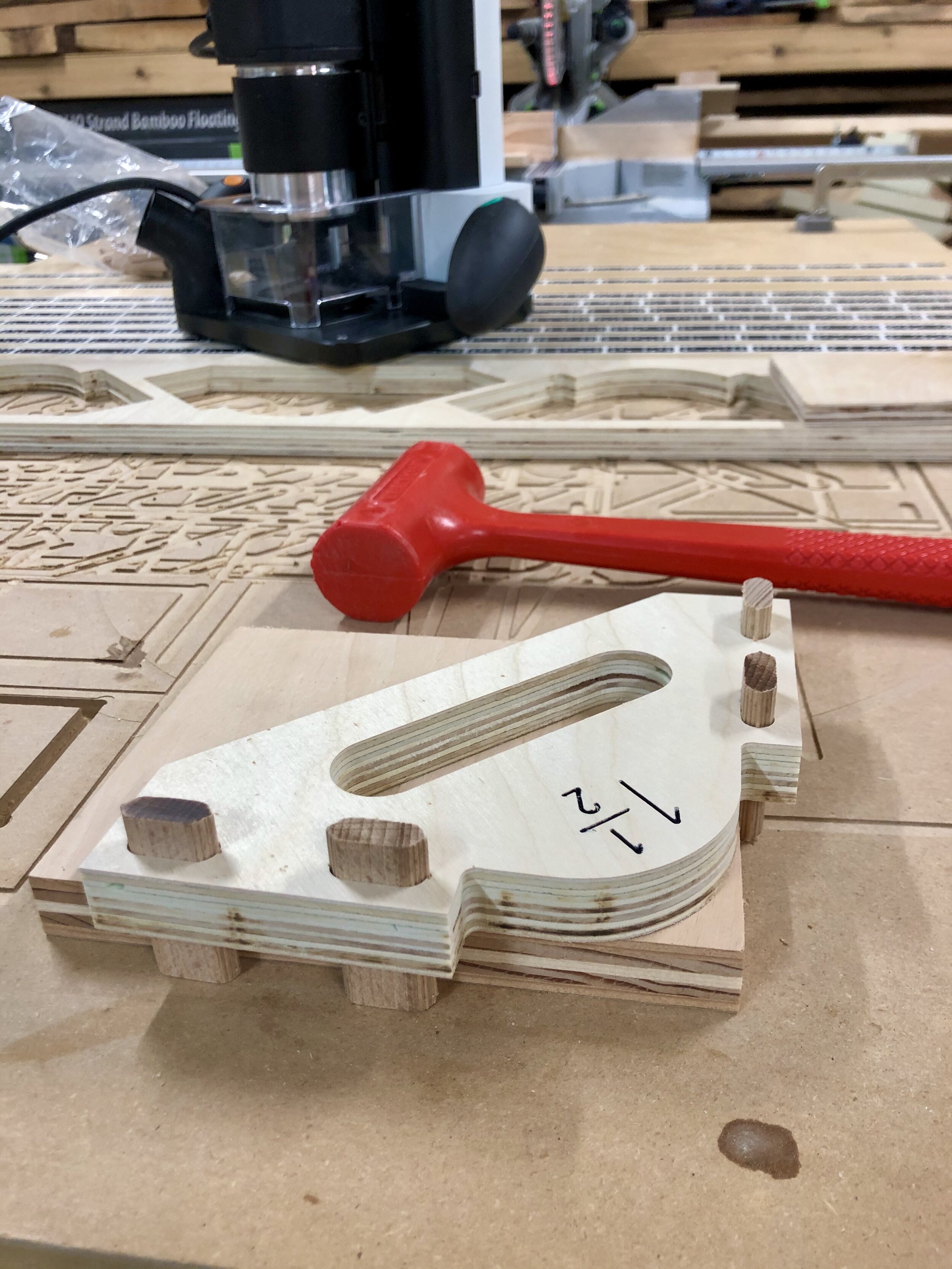
Hold Down Tabs
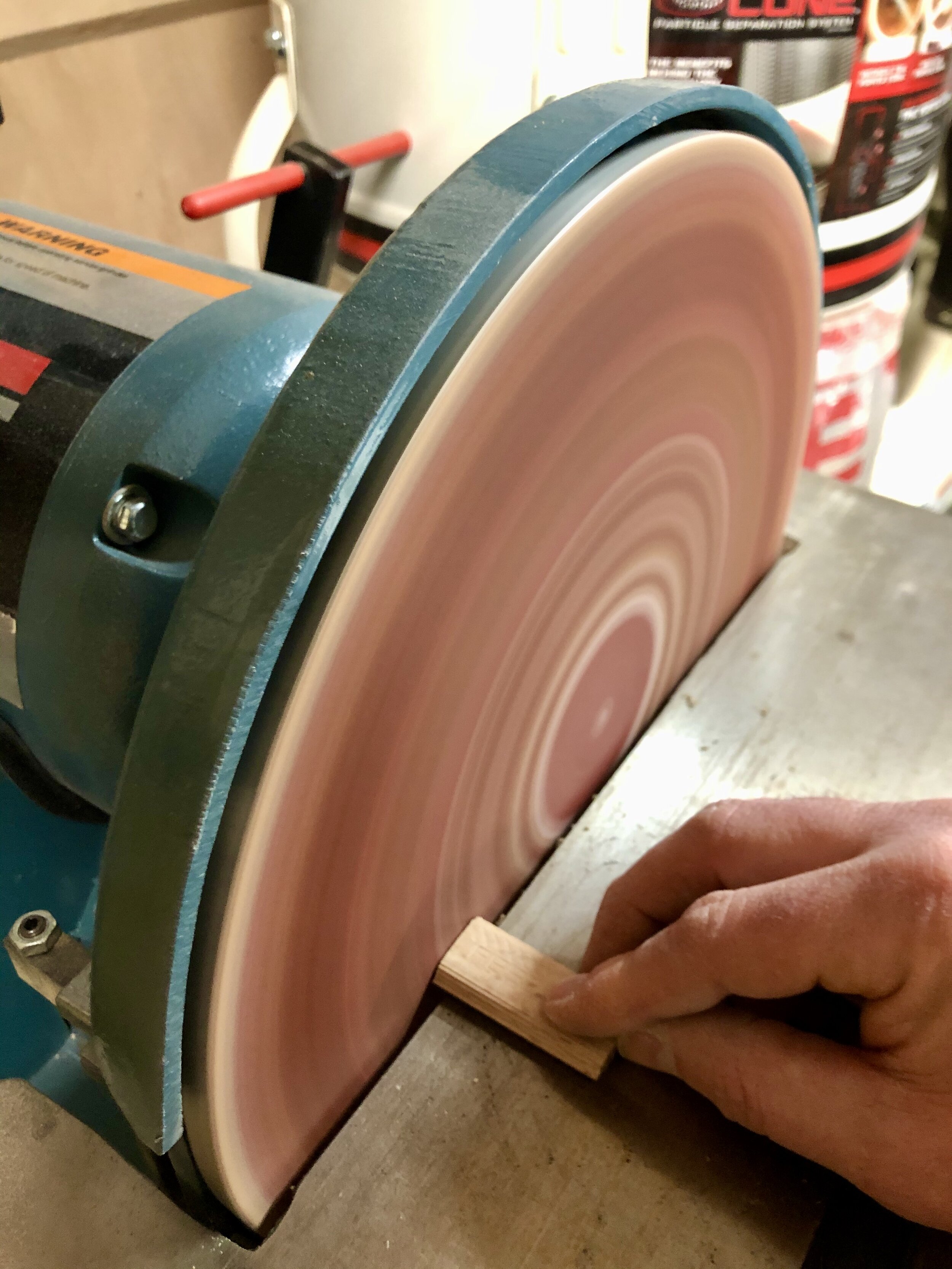
Cut out the tabs from 12mm (1/2”) plywood
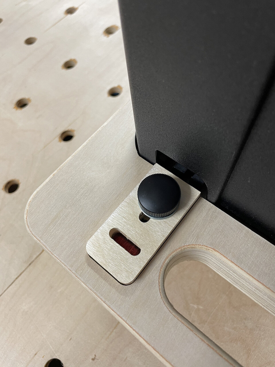
With a systainer in place insert the front tabs. They should be a tight fit since they will be permanently secured (see NOTE below)
The side tabs should be a snug fit but still able to slide back and forth in pocket. Light sand if needed. (see NOTE below)
NOTE: You may also have to sand the bottom or top edge of the tab that goes over the “pins” on the systainer box depending on the thickness of the plywood and the systainer model you are using. You want the tabs to sit flat in their pockets to the systainer can be inserted and removed easily.
Drill a pilot hole in the front tabs and secure them with a screw
Don’t glue them in place just in case they need to be replaced in the future
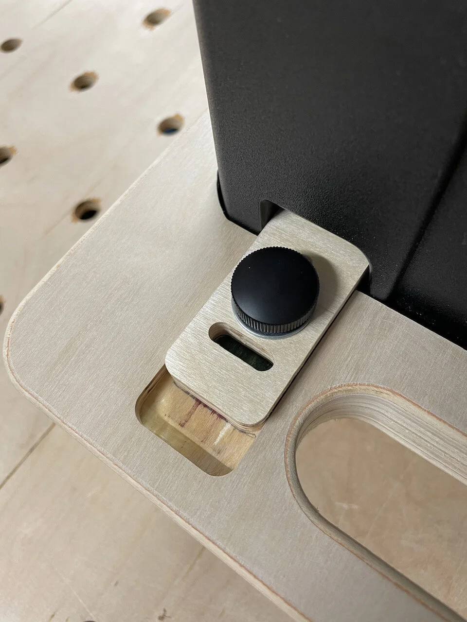
With the side tabs fully slid out (so that they are flush with the edge of the systainer cutout) take a pencil and trace the slot that goes from left to right.
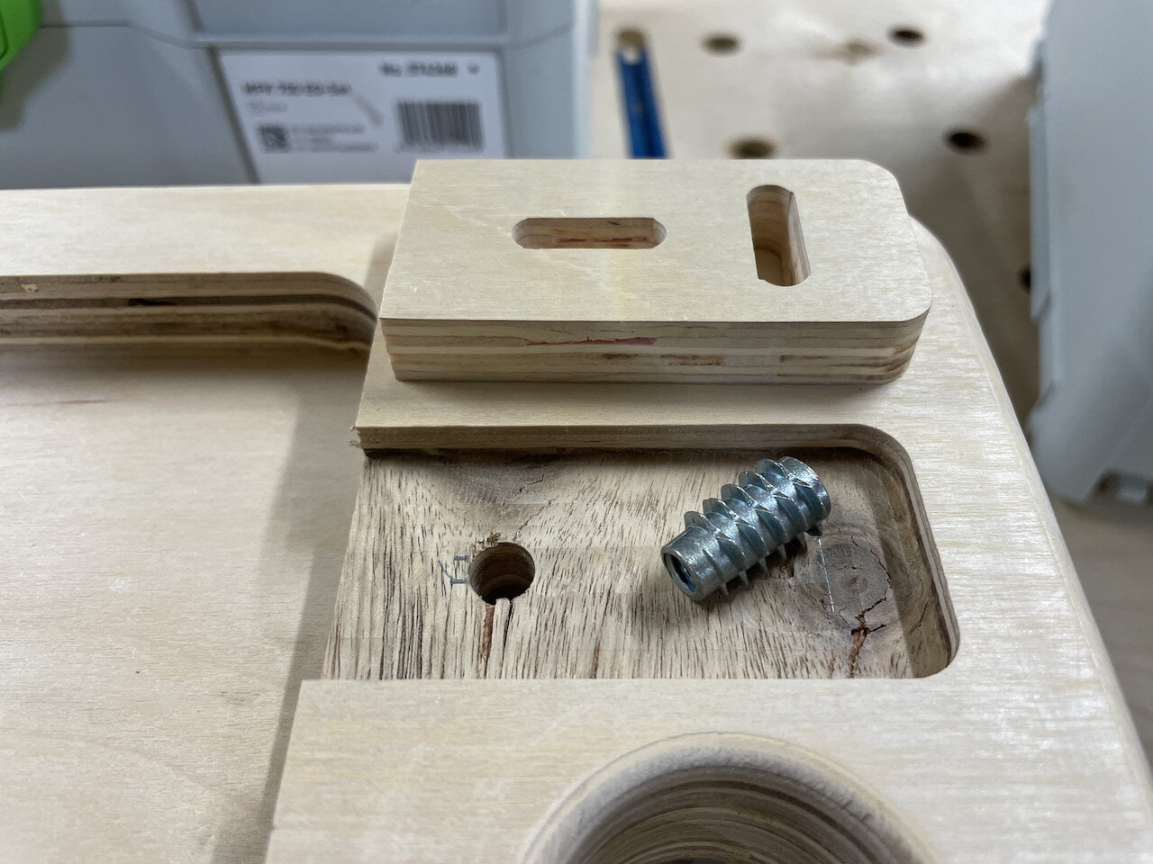
Drill a hole in the inner most part of each slot for the threaded insert
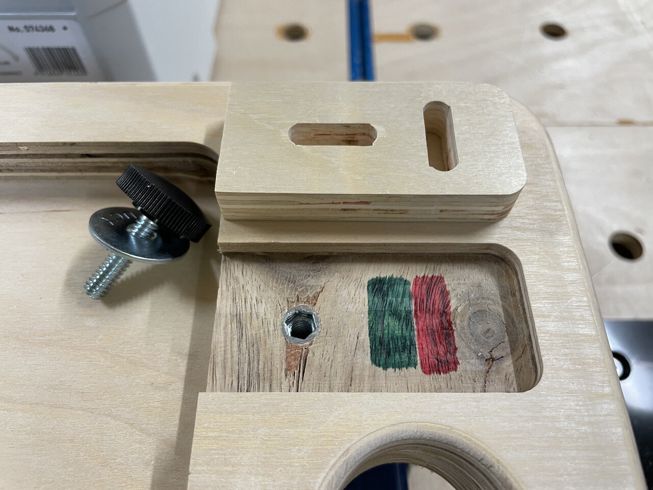
Use a hex wrench to screw in the threaded insert so that it is flush
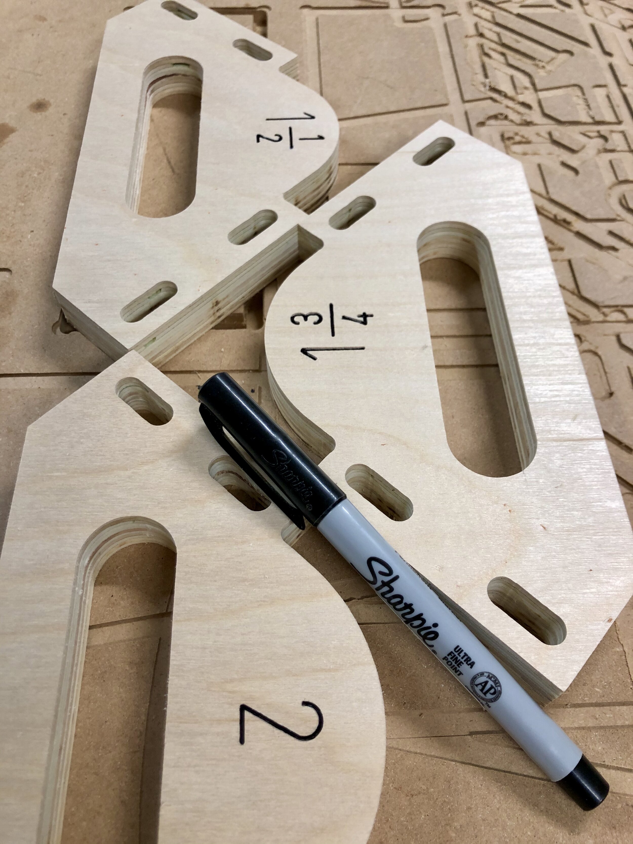
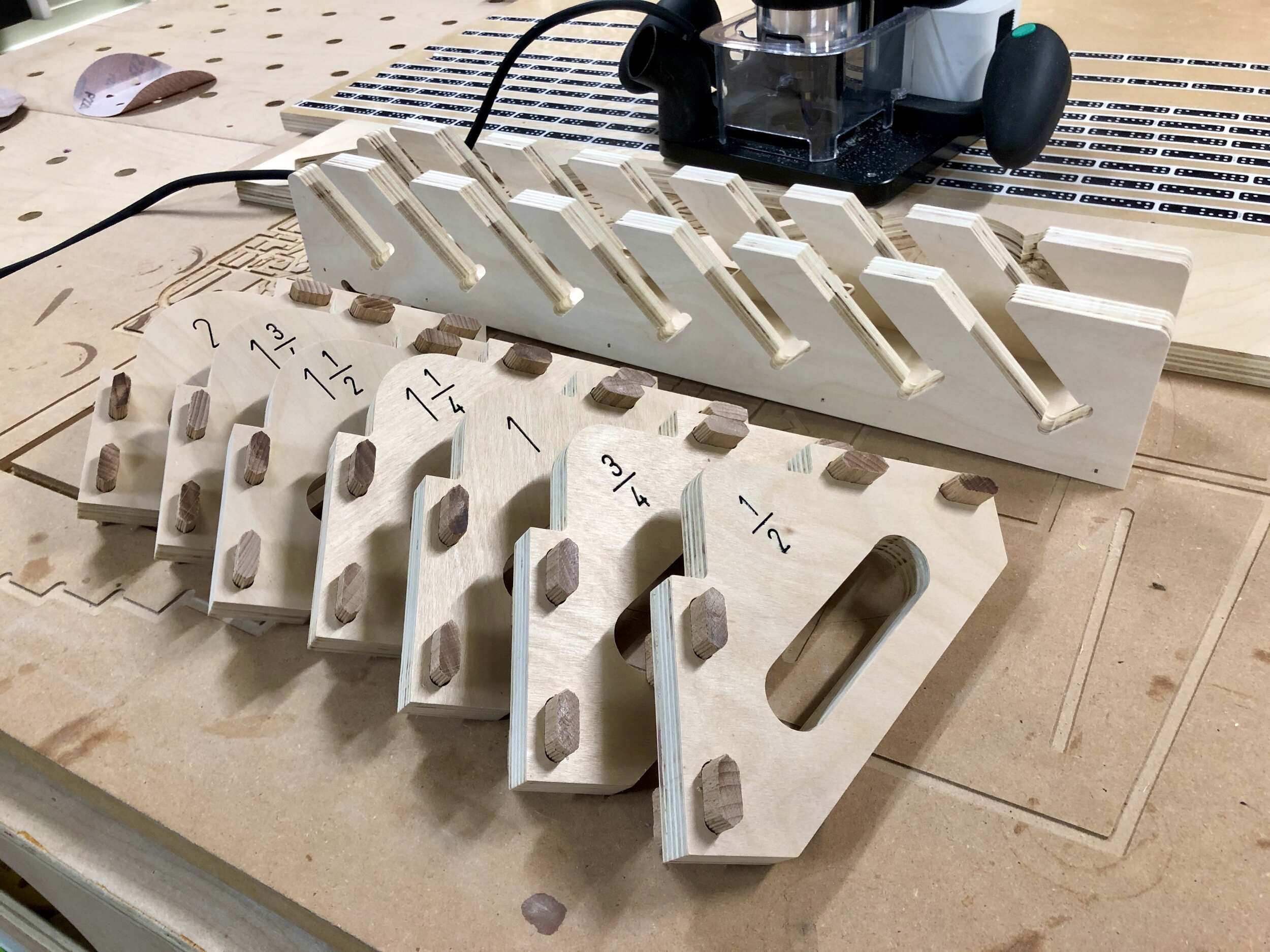
OPTIONAL - I put a systainer in place and open and closed the side tabs marking where it was secure and not secure, then took the tabs off and used green and red sharpies to give a visual indication when the tab is in a locked and unlocked position.

Admittedly you’ll have to fine-tune the tabs to work with the model type of systainer you have but I have made the cutout for the systainer compatible with both the Systainer3 and previous version.
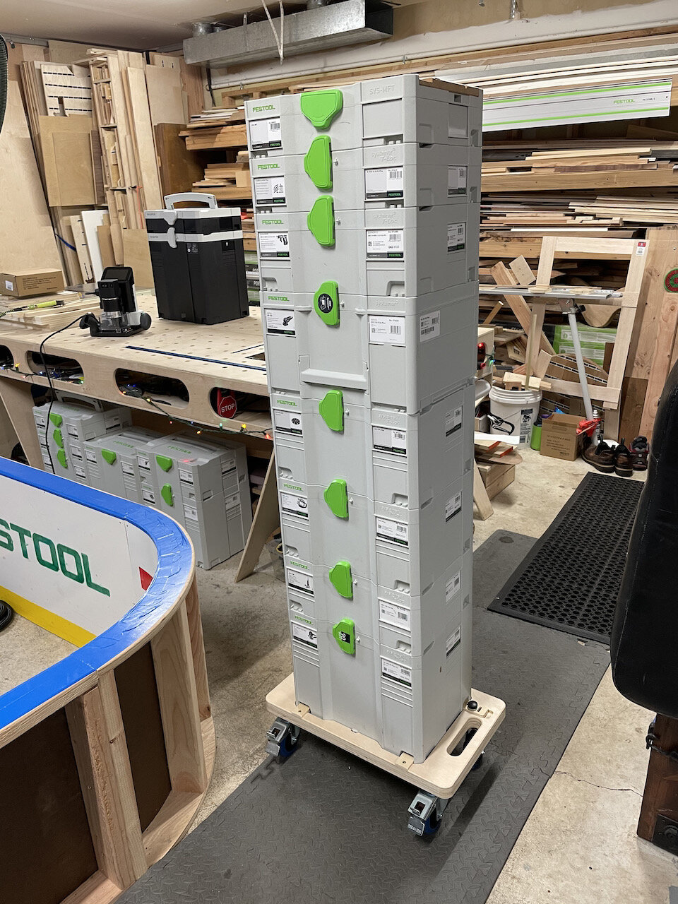
This should be extremely helpful for me in and out of the shop and I hope it is for you as well.
I have posted the files on ShaperHub
As always, I hope this helps.
Cheers,
Lee