Origin

Let There Be Light!

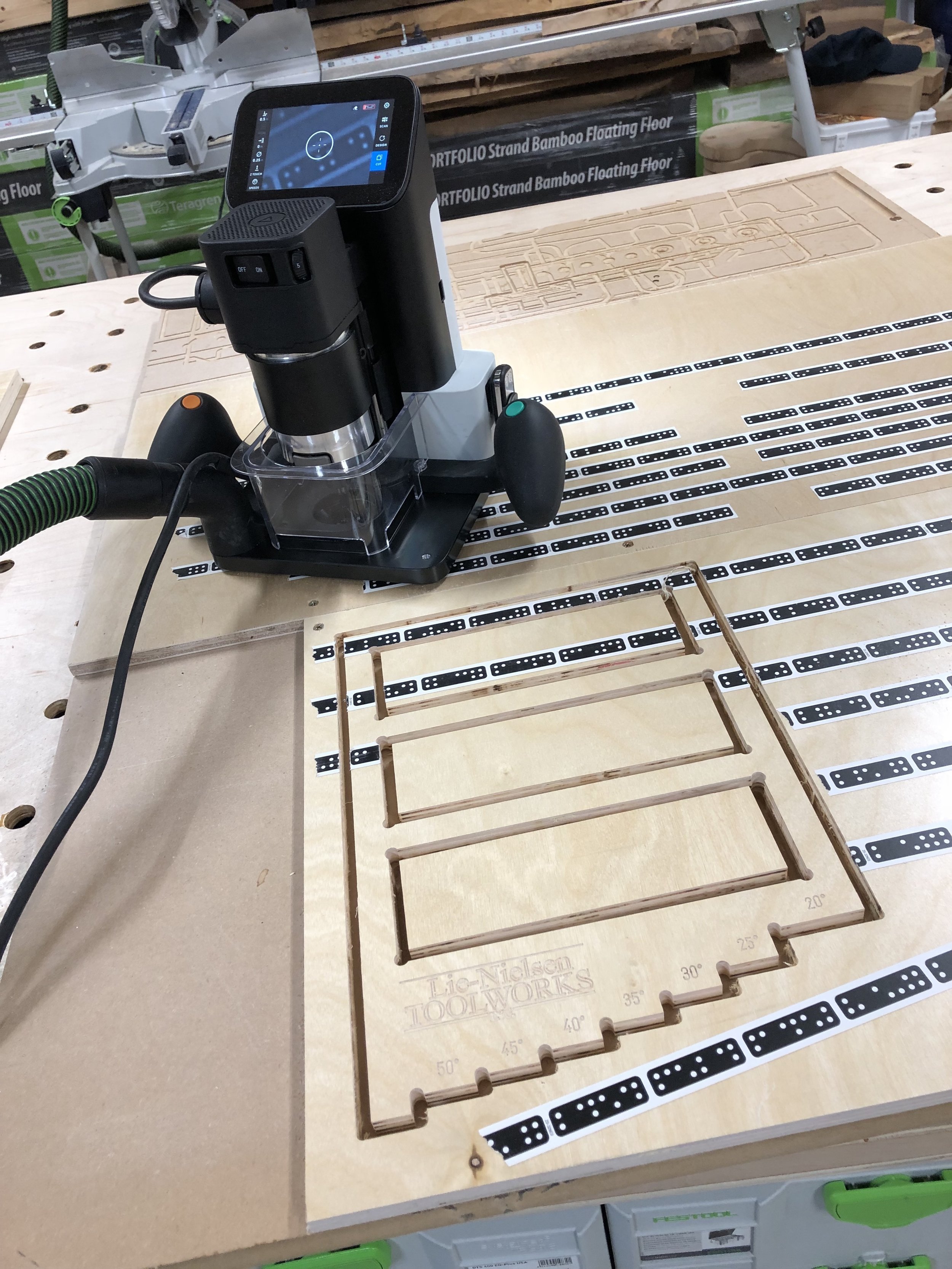
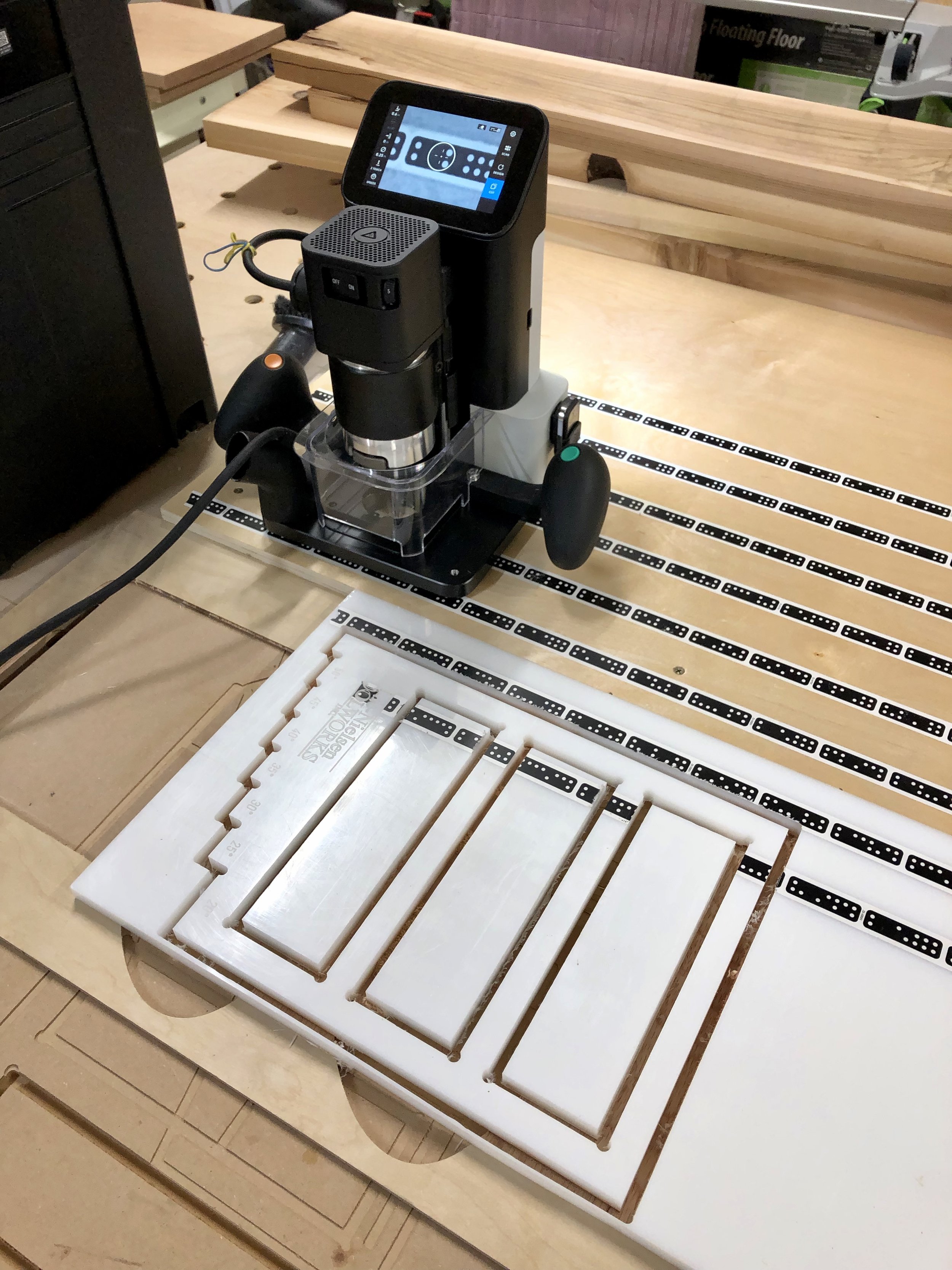
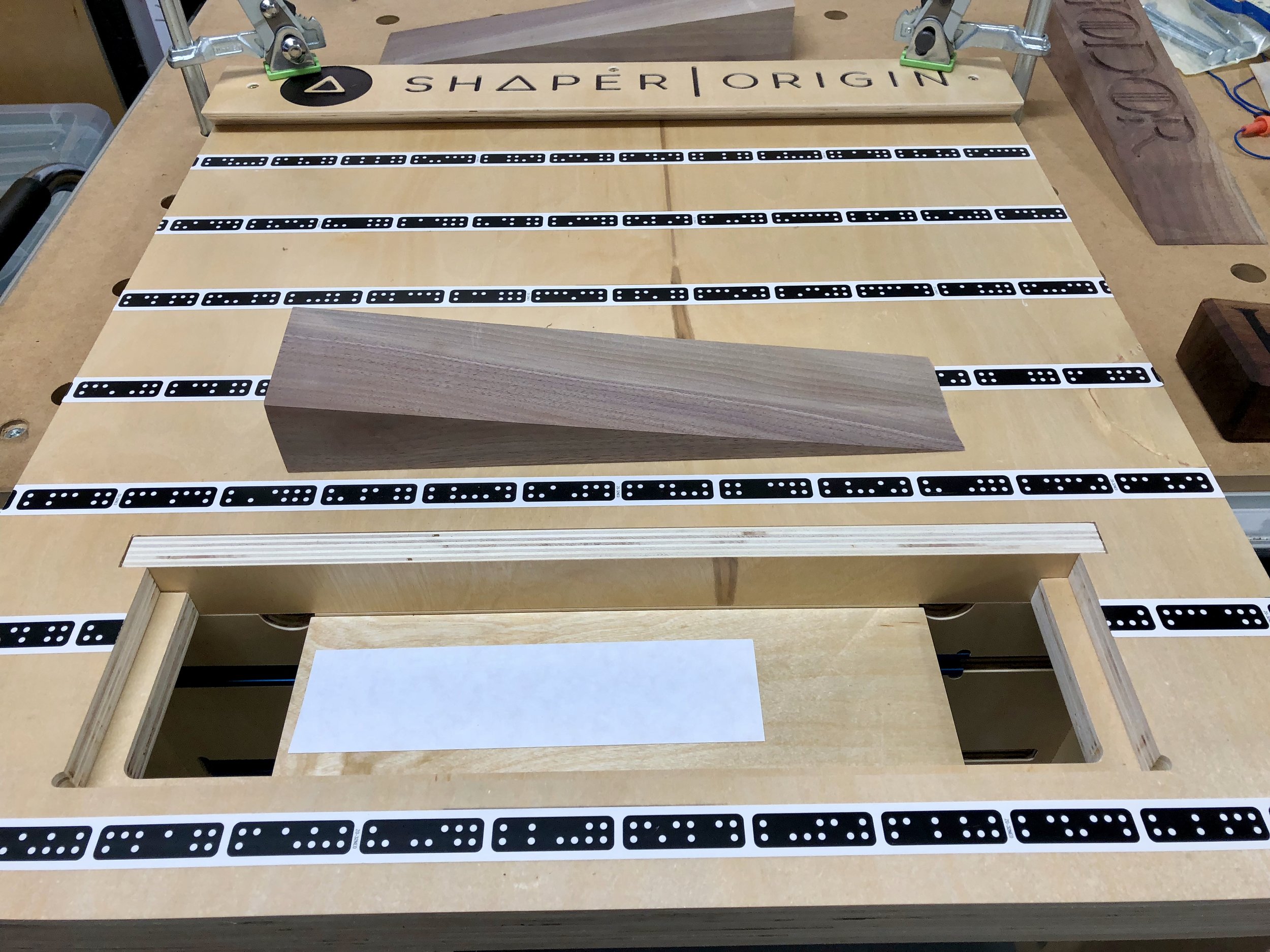
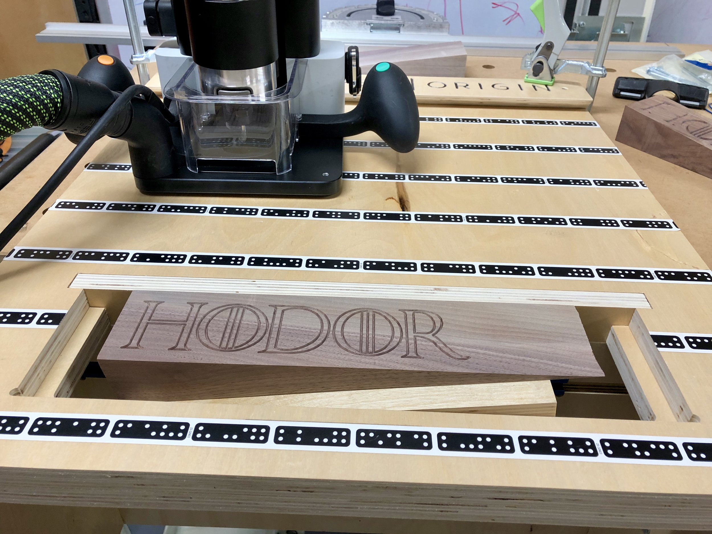
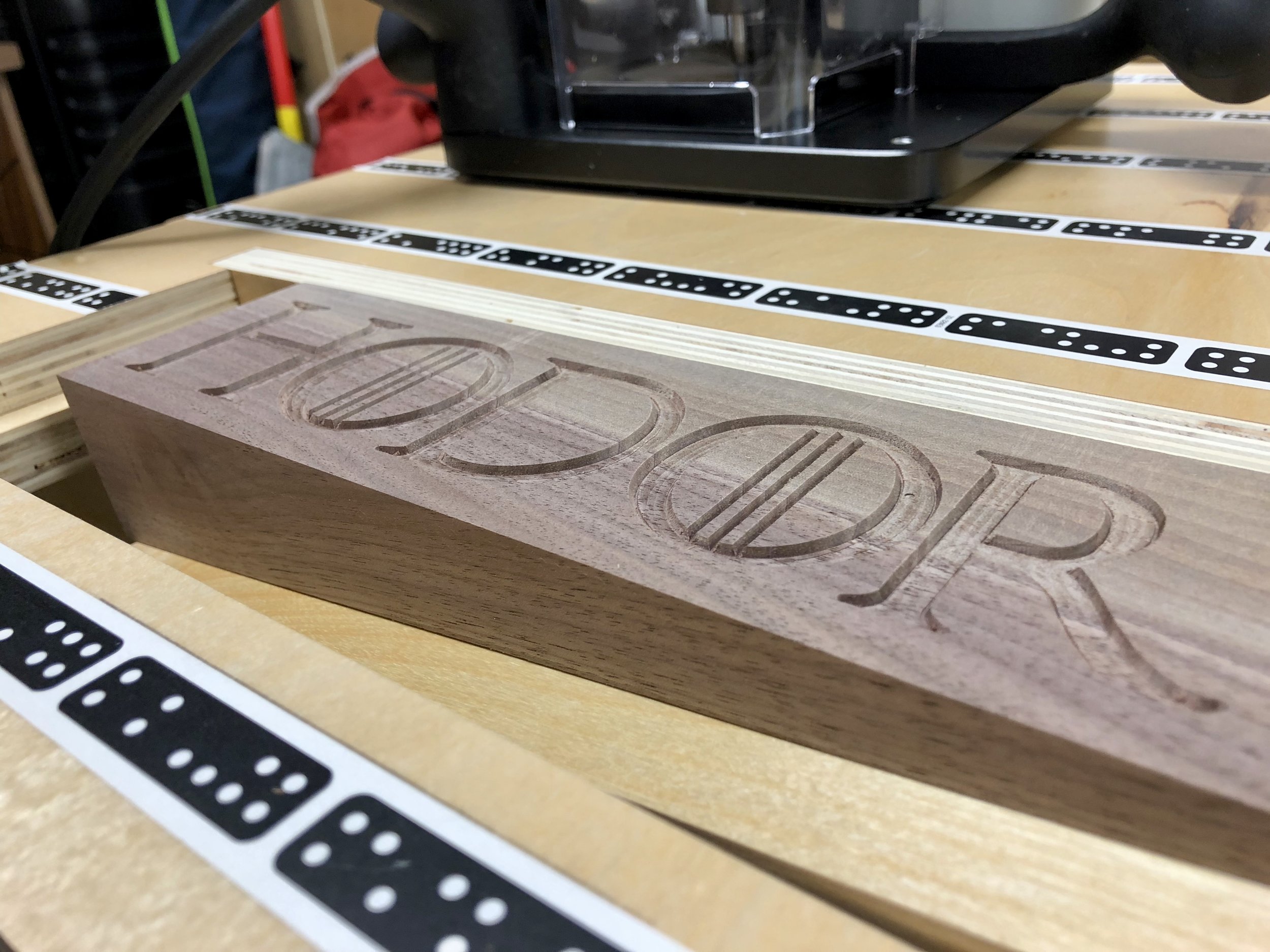
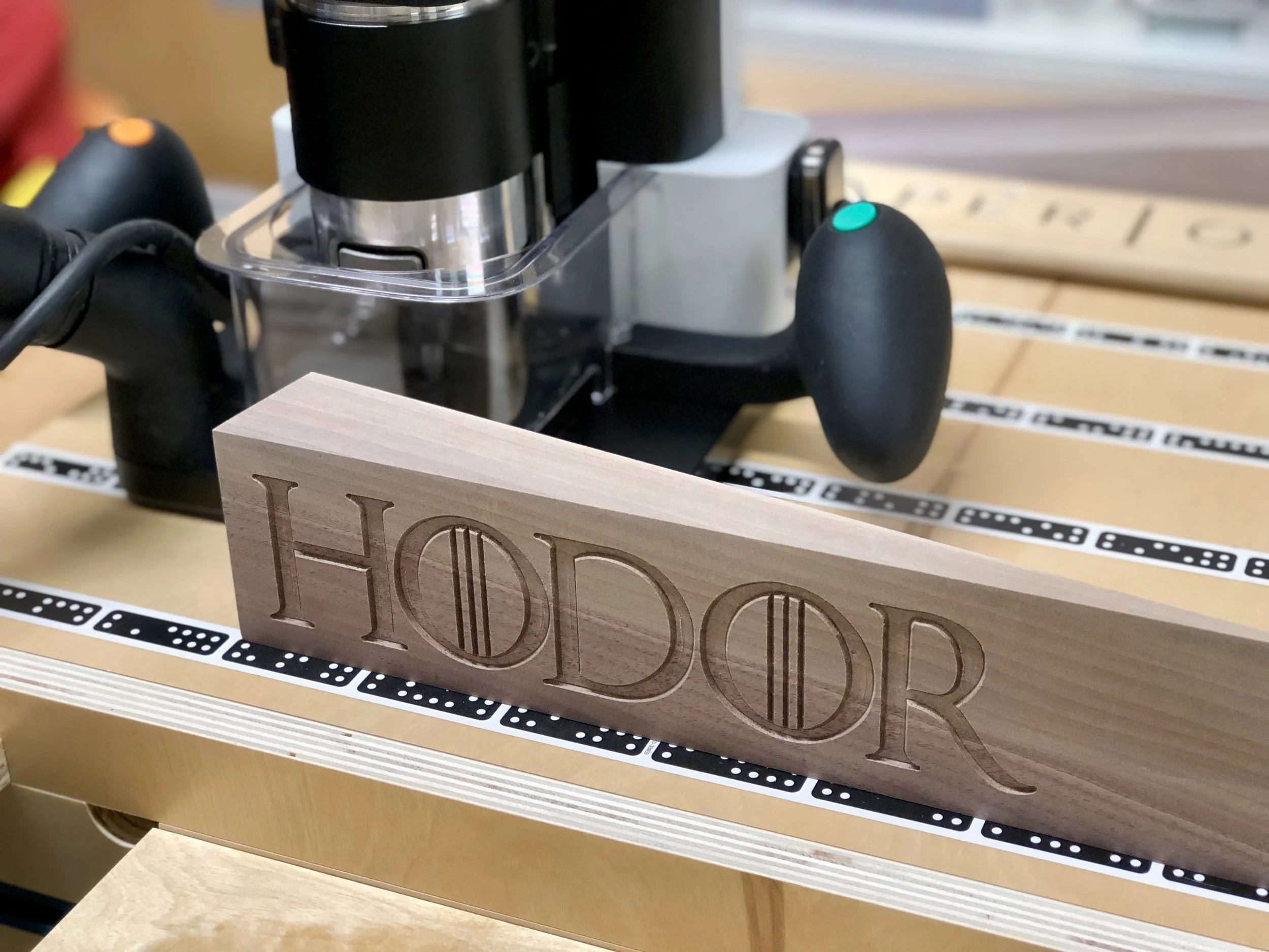
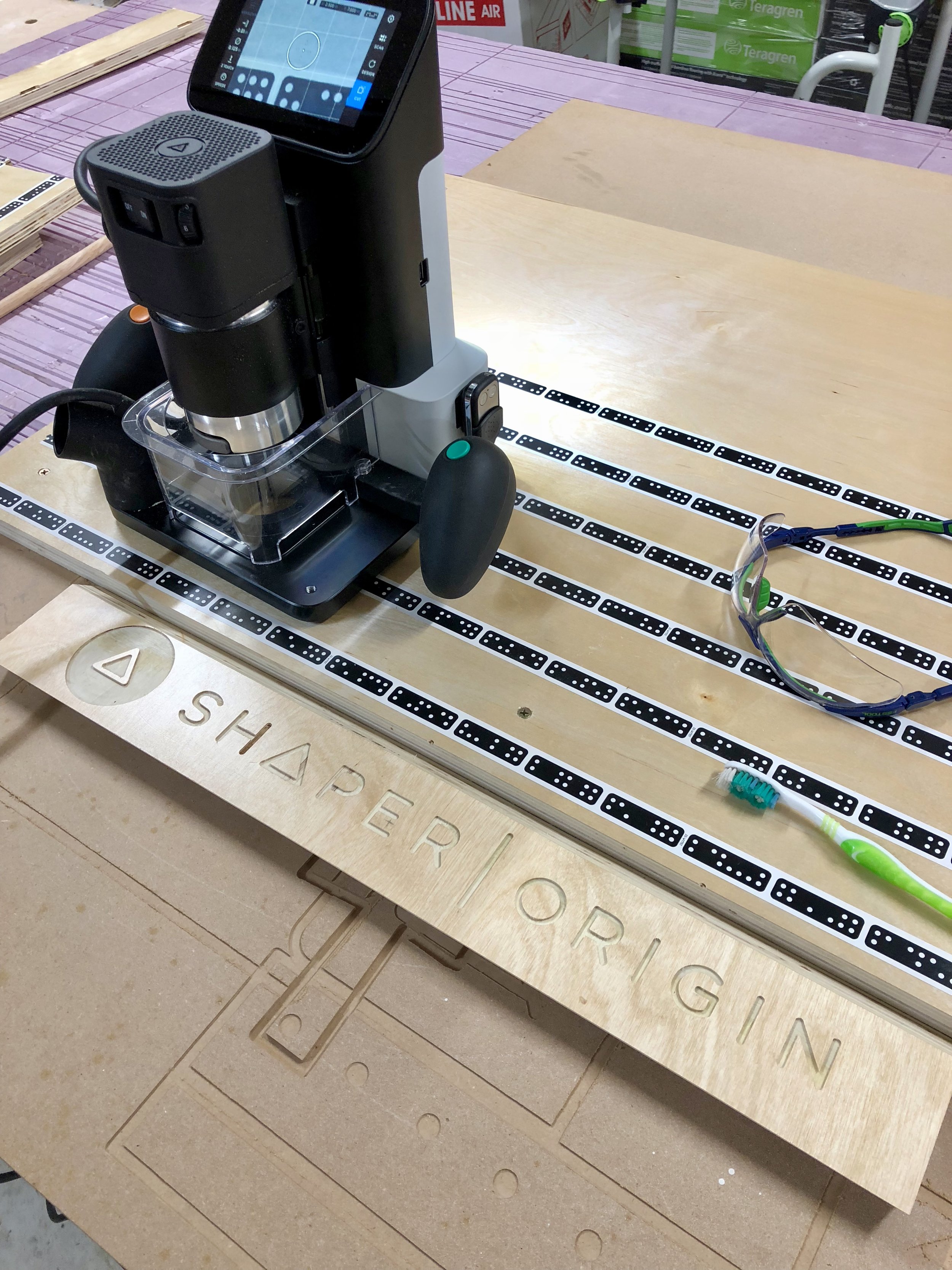
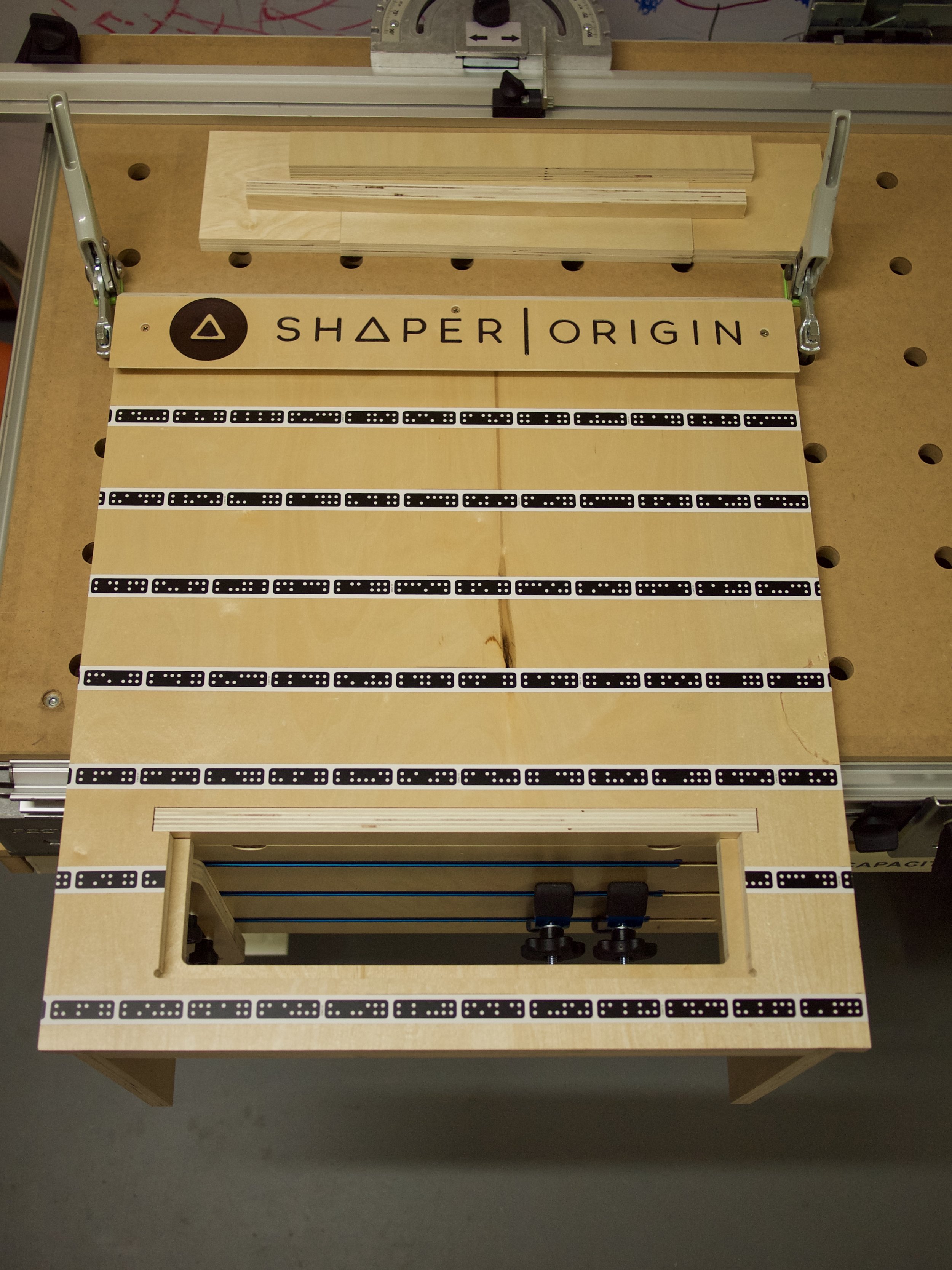
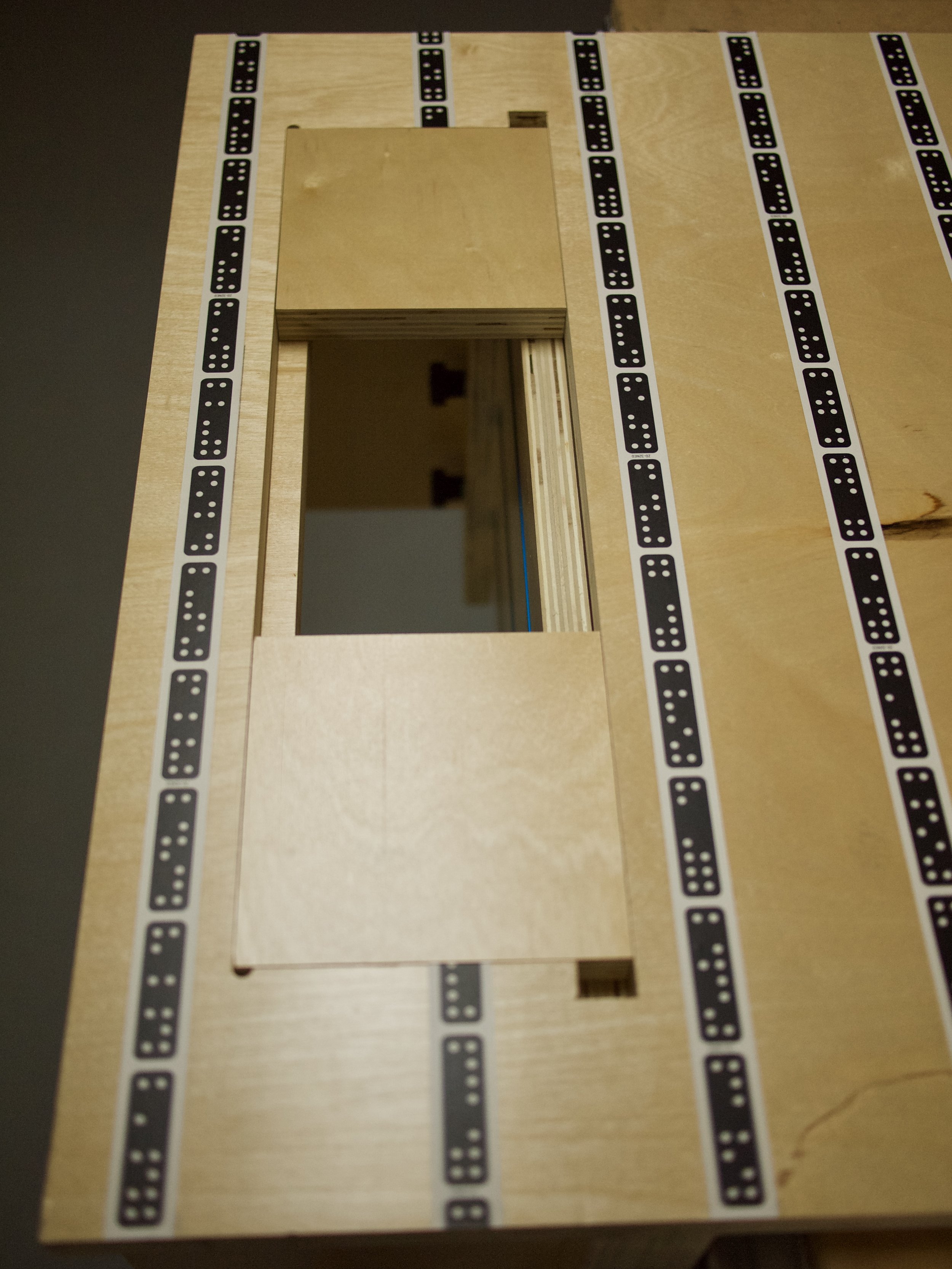
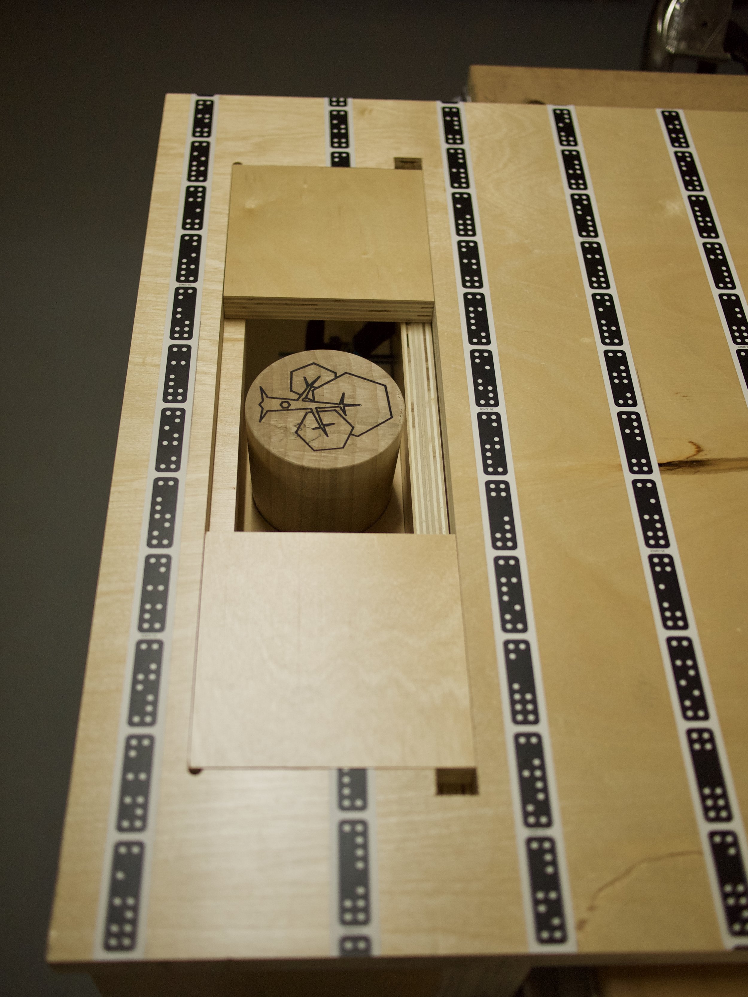
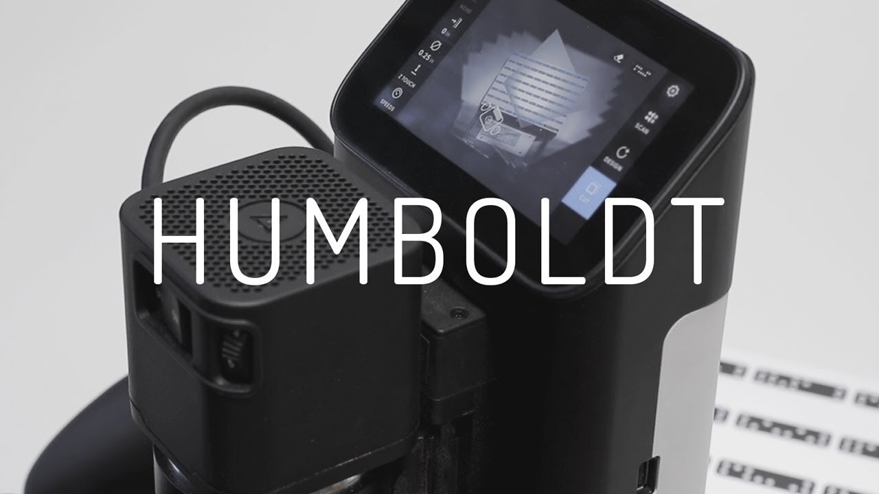
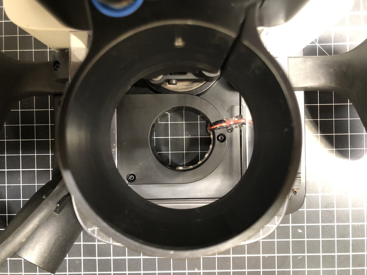
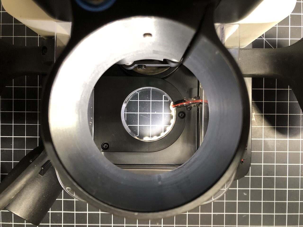
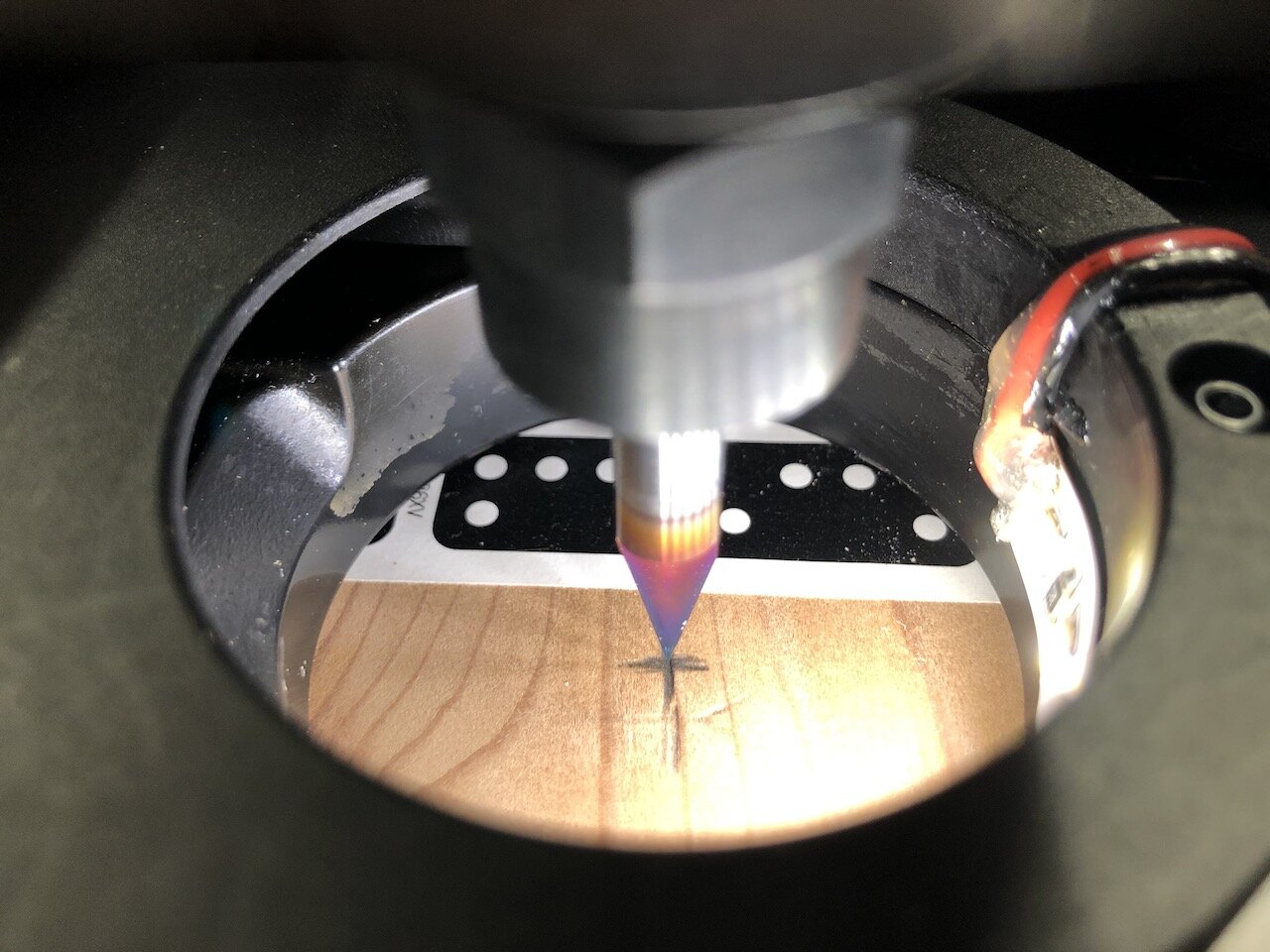
With the new Shaper Origin firmware update (Humboldt), creating virtual Grids has been overhauled and now you can create grids in the middle of a work piece by probing reference marks drawn on the surface of the material. As soon as I saw Sam from Shaper demo this I immediately thought “It would be great if there was a light closer to the bit so you could see the tip of the engraving bit centered over a reference mark.”

I had some left over LED strips from some previous projects and wondered if there was a way to power this on the Origin. I considered powering the LED lights via a plug-in cable but it seemed a bit of a pain to wire up a whole power supply for such a small amount of LEDs. I also considered powering them from the the Origin itself (for about a minute) and then thought “Well that will void any kind of warranty, etc. etc.” and didn’t really want to take the Origin apart (yet ;-) ).

So then I thought “Surely, there is a way to power these few LEDs from a battery.” Unfortunately, I had some High Output, 24V lights so I needed to figure out a way to power them from batteries. Now, I will be the first to admit I know nothing about electronics, and I’m not even that good at soldering, so after Googling “how to power LEDs from batteries” I purchase the following:
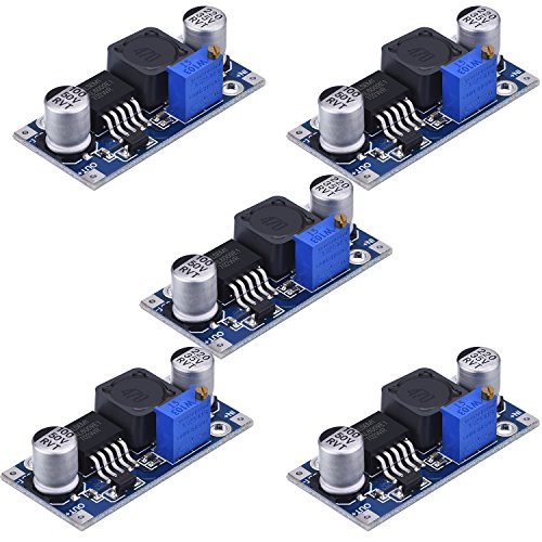
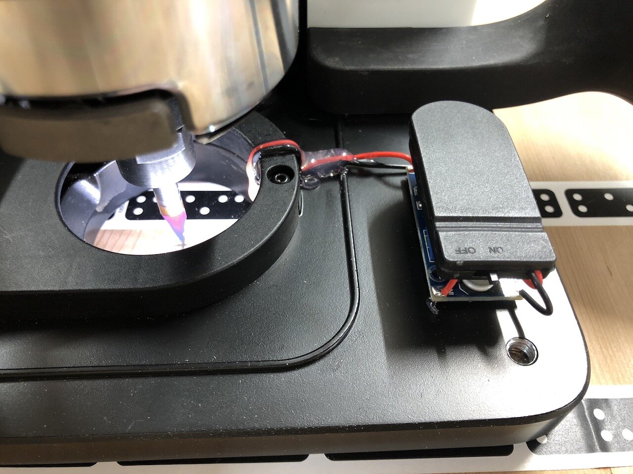
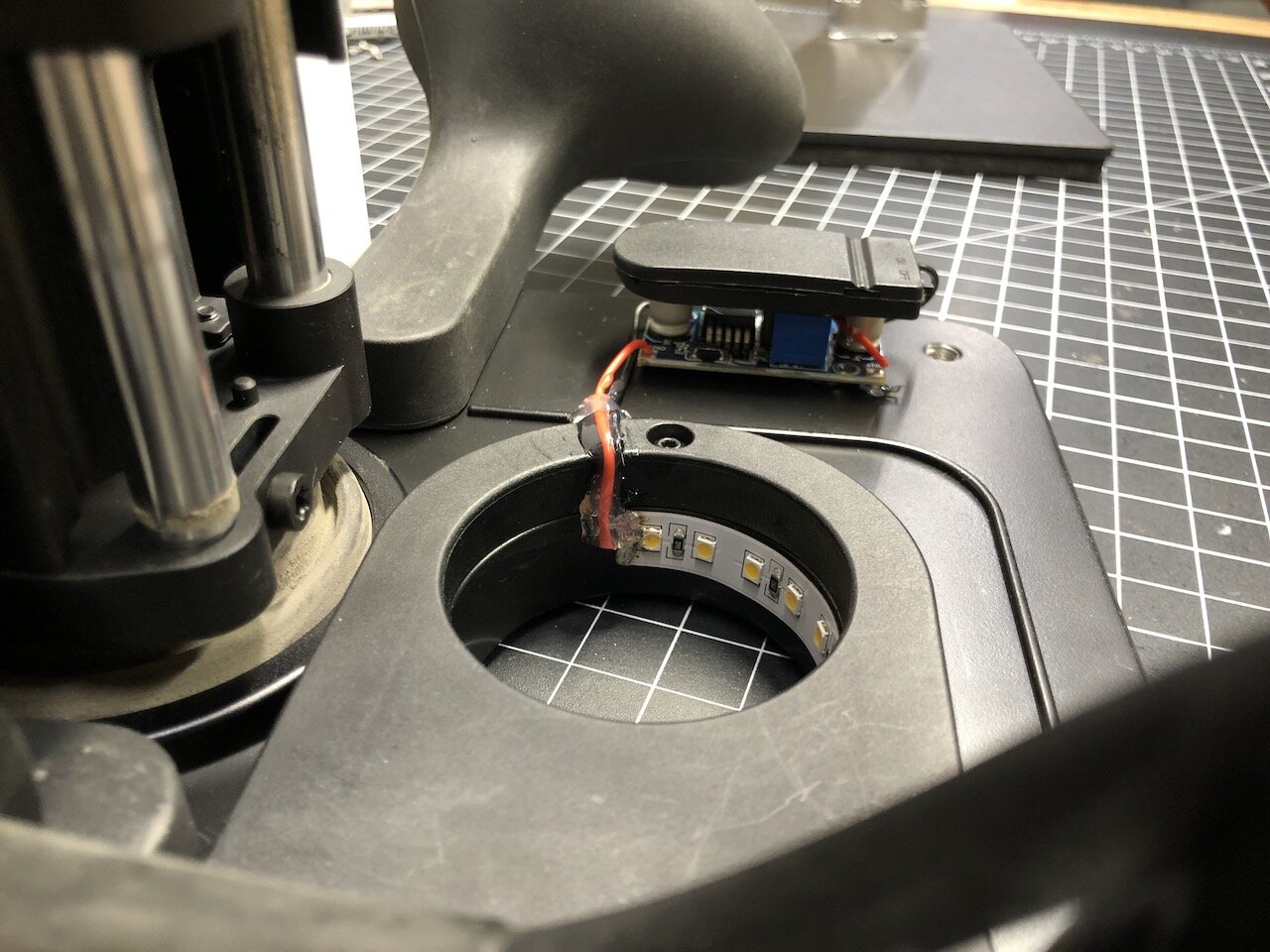
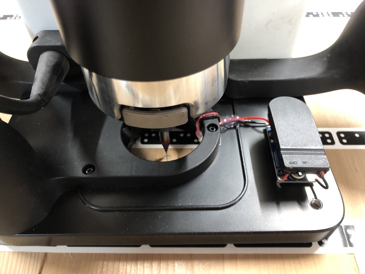
For this experiment I’m using two CR2032 batteries that are 3V each. So I’m stepping up from 6V to 24V. I’m also only using one section of the LED strip, which consists of 6 LEDs.

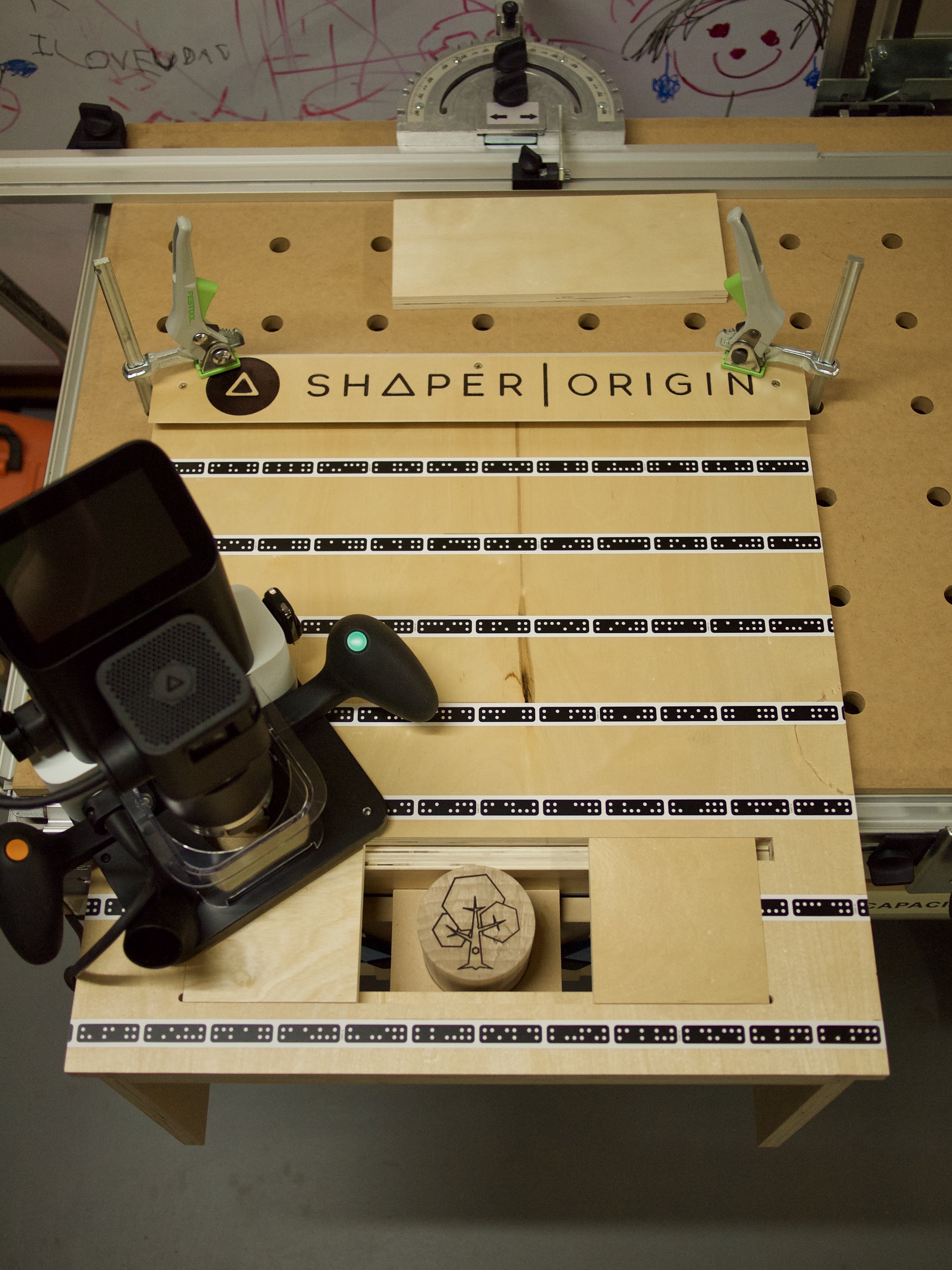
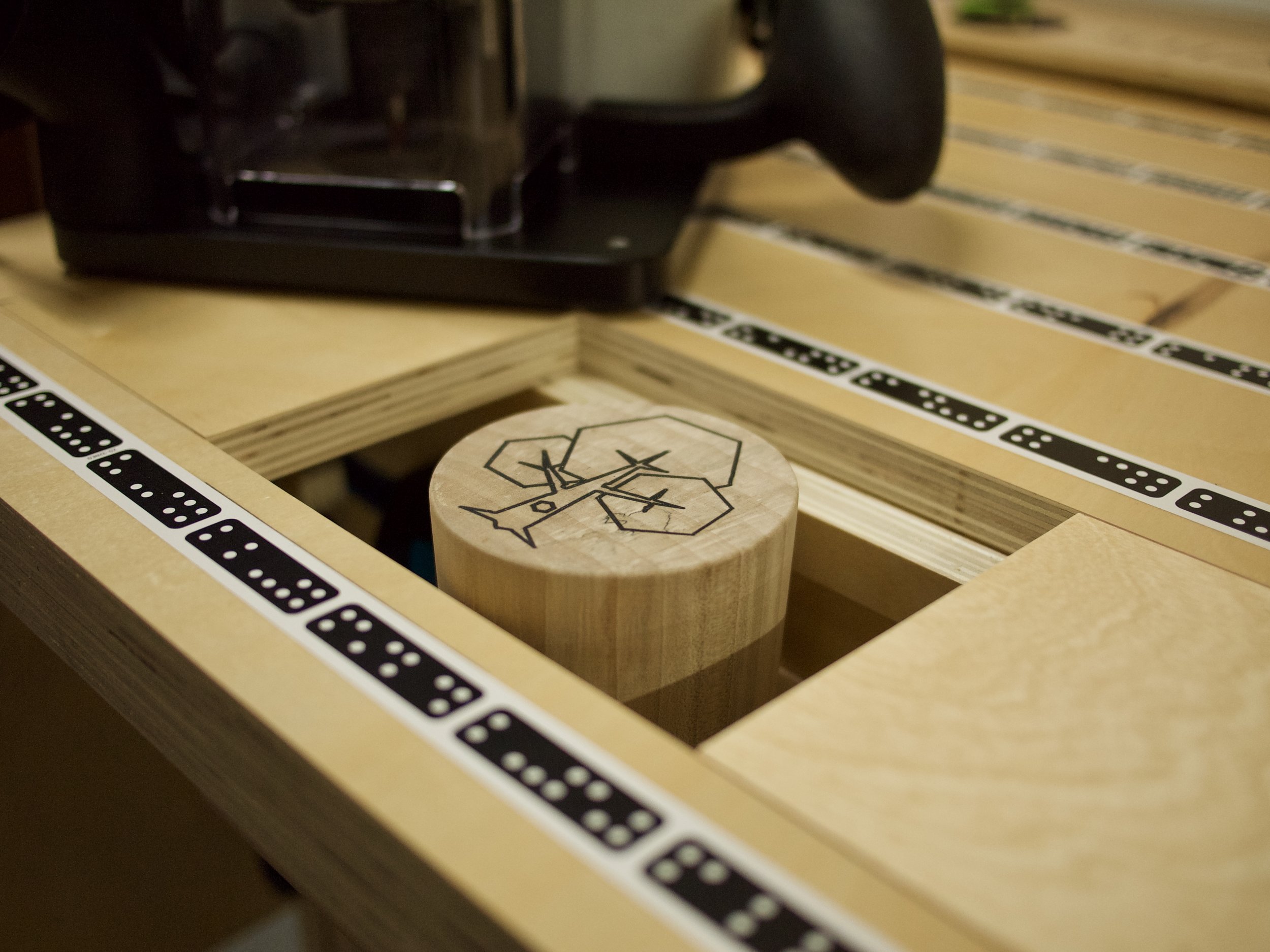
I’ve very aware that the LEDs and wiring are “in the danger zone” of the router bit so I’ve hot glued the wiring down and I’ll be keeping a very close eye on it.

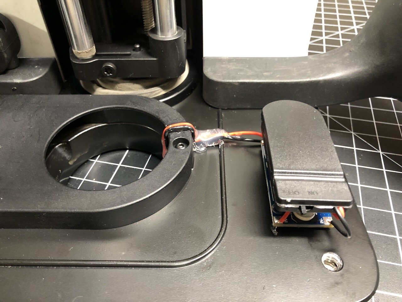
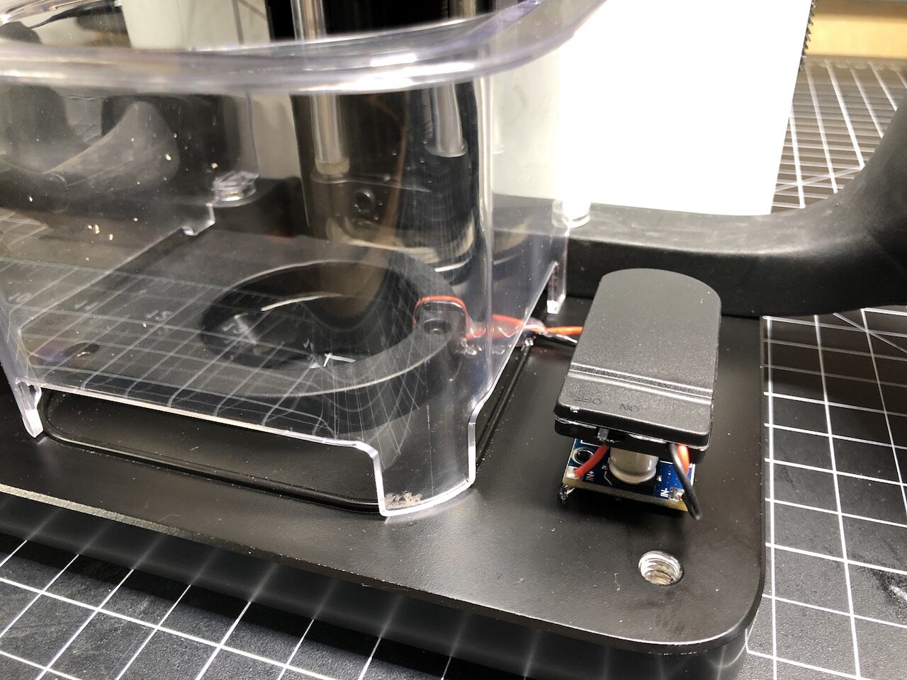
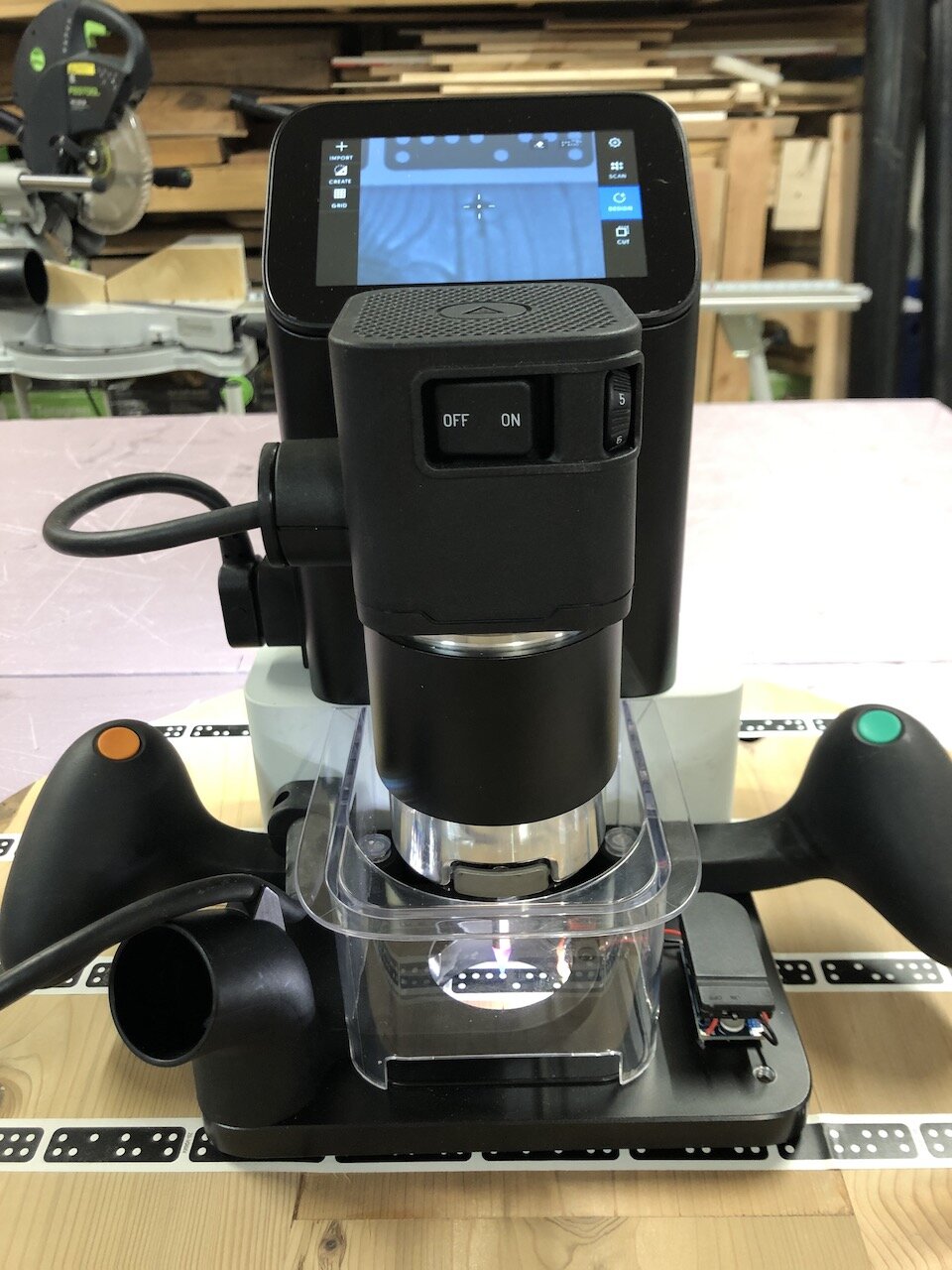
I’m still playing around with it but the initial concept works. For some reason the voltage is dropping after about 10 seconds, which causes the lights to dim and then turn off. I may end up switching to a 9V battery at some point. Ideally if I had a 3D printer I would design and print a case for the step-up converter, batteries and switch so I didn’t have to worry about dust but this is just a prototype.

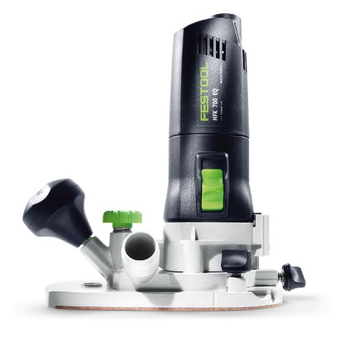
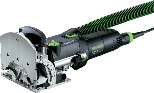
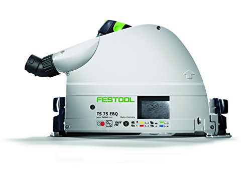
With any router it’s so hard to see the bit when it’s lowered into a cutting position so I’m actually considering applying this mod to my other Festool routers so I can see more clearly where the router bit is at any point. We’ll see how the LEDs hold up but if I were to start from scratch I would probably use some waterproof LEDs since they are encased in a plastic that would protect them. Of course, the downside is that this stick out further, but anyway we’ll see how they work out.

Anyway, if you have any tips, tricks or comments that can help please leave them below.

As always, I hope this was helpful.

Cheers,
Lee


Tools and Materials used


Back to the Drawing Board

Christmas has come and gone and it was a good one. I really enjoy making gifts for people because I can make something unique and personalized that they could not normally get. Plus, it’s just another reason to do something that I love doing.

My kids (ages 5 and 7) are very into drawing so this year I decided to make them custom drawing boards.


This project was not only rewarding for them but I also learned quite a few things that I would like to share with you…


File Management

I had collected some ideas from Pinterest and Google searches and then designed the drawing boards in Adobe Illustrator. Because it consists of two boards with CNC work on three of the surfaces I tried to stay organized with the layers in the .ai file. I created a layer for each surface and one for the basic outline of the board with handle cutout. This was critical for maintaining alignment of the shapes between the layers. Had I done this in separate files I would have undoubtedly messed something up.

Once I was finished all of the layers I did a Copy and Paste in Place of the objects within each layer and the basic outline layer into a separate file and then save that file as the .svg for each surface. In my experience hidden layers still expose themselves in the .svg file when making cuts so saving the layers into separate files eliminates the clutter when trying to cut.


Cut Management using Shaper Origin

  1. Save time by cutting all of the main boards with the track saw (or table saw). Obviously, I could have cut the outline of the main board with the Shaper Origin (SO) but it would have taken a lot of time and as I’ve mentioned in past posts, cutting long straight cuts can be challenging. I also got a chance to use my new Corner Jigs for rounding the corners.

  2. Set up a template to hold the pieces in the same position. Since the three surfaces I had to cut on the two boards were all being cut from the same size piece it made sense to set up a template to hold the pieces in the same place every time. That way I could set up the Grid on the SO one time and place the various .svg file in the same location to make sure they all aligned. I kept two boards screwed down (in my case a top and left board) which never moved and had marker tape on them.

  3. Add marker tape to each piece using “Add to Scan”. Since I did lesson learned #2 (above) I only needed to add marker tape to each new surface and “Add to Scan” to maintain the grid.

  4. To cut through the outside edge of the piece create lines and shapes that extend past the main object outline.

  5. Use black outline with white fill for small hole pockets. Even though the pencil and marker holes are not through holes, in order to use the "Helical” function on the SO you’ll need to use and Inside cut. This wasn’t a big deal to change on the SO itself but since there were quite a few holes to cut it will save you time when cutting if the file is set up correctly.

  6. Because of lesson learned in #4, set up a Grid on the SO that allows for center alignment. I couldn’t left align the .svg file since I have cuts that extended past the edge of the work-piece. To center align, divide the work-piece in half and then sub-divide that into equal units. In my example the boards are 600mm wide so I created a grid in 10mm increments so I could find center at 300mm.


Overall, this was a great learning experience. I’m please with the result and, of course, extremely happy with the kids reactions. There have already been a number of people on Instagram and Facebook asking if they can buy one so I think I may make a few of them to sell in my store so keep on eye out for that. ;-)


I hope everyone had a fantastic Christmas and will soon have a Happy New Year.

And as always, I hope this was helpful. ;-)

Cheers,

Lee

Tools and Materials used


Sharpening Station

As everyone knows, a chisels or block plane is only as good as the sharpness of the blade. Ever since I started getting into Lie-Neilsen chisels and planes I’ve been wanting to make an Angle Setting Jig for the honing guide.

Here are the docs provided by Lie-Neilsen:

Sharpening Instructions PDF

Angle Setting Jig PDF

The honing guide came with the measurements for the chisels or blades in order to achieve the desired angle. I know most people just use a scrap piece of plywood with some smaller blocks. However, I thought “surely someone must make one.” To my surprise, no one does. So I drew up some plans in Adobe Illustrator and used my Shaper Origin to make one.

Click for SVG file

Click for SVG file

Click for SVG file

Click for SVG file

I started by making a prototype out of plywood just to see if it was going to work. The top is cut from 1/2” thick material so the stones will stick up slightly. Ultimately, I didn’t want it out of plywood because it was going to get wet. However, it was fine for proving the concept and dimensions were going to work.

I made cutouts for the three Shapton sharpening stones I have (1000, 5000 and 8000 grits) and angle settings for 5 degree increments from 20 to 50 degrees across the bottom. The grooves on the back piece allow for drainage and weeping holes on the sides for excess water.

I chose to use HDPE (the same stuff as plastic cutting boards) for the final version. Since this was going to slide around I added rubber feet to the bottom. I also used black epoxy to fill in the lettering and numbers.

Lessons learned

  1. Because of all of the drainage grooves in the back piece it tends to warp or bend up slightly so if I was to build another one I might do less grooves.

  2. Alignment of the top and bottom pieces is critical for the correct measurements and can be a bit tedious.

Now it’s time to sharpen some blades and put the tools to work.

As always, I hope this was helpful. If you have any thoughts or comments please leave them below.

Cheers,

Lee

Tools and Materials used

Horizontal Support for Shaper Origin "Ultimate" Vertical Workstation

I know it’s been a while since my last post but time flies when you’re having fun (or working on a lot of different projects).

Anyway, I’ve been thinking about making some Xmas presents and I was inspired by something I saw from “Mike the Maker” on Instagram. My friends and I are into the Game of Thrones show and I thought it was pretty clever to make a doorstop with the word “HODOR” engraved on it. I could absolutely use the Shaper Origin to do the engraving but I was trying to figure out how to engrave something on a wedge shaped piece of wood.

Since the width would fit in the opening of the “Ultimate” Vertical Workstation (UVW) I made I just needed to figure out a way to hold it so the surface of the wedge was level with the top surface of the UVW.

My first attempt was using the vertical support to set the angle and then a block of wood to support the wedge. It didn’t work very well because it was difficult to clamp the thick block, which is when the Horizontal Support was born!

I built a three versions before settling on this one. v1 had parallel sides which limited the angles side to side that I could use it at. v2 had angled sides but was tall and wide. This stuck out a bit too far when mounting it on the side when not in use (you’ll see later) and the slots for the clamping knobs were not distributed at the same width as t-tracks are vertically. I’ll also show you why this is important in a minute. So here is v3…

Here is the SVG that I used…

Click on image for full .svg file

Click on image for full .svg file

Cutting and Assembly Steps

1. Cut the mortises for the Dominos in the top using the Shaper Origin. Because the top is quite small it was difficult to cut them out with the DF500 after the top was cut out so I researched the exact size of the holes made at the various settings and added tight mortises on the outsides and a medium mortise for the middle. (Use a 1/8” bit, Inside Cut, 2 passes at 7mm and 15mm deep, 0” offset) [please excuse the holes in the scrap piece of plywood I used shown in the pictures]

2. Cut out the pockets for the supports. These are 18mm wide but check the thickness of your material and adjust with offset accordingly (Use 1/4” bit, 1/4” deep, Pocket Cut then Inside Cut at 0” offset)

3. Cut the slots for clamping knobs. (Use 1/4” bit, Outside Cut, 0” offset, 3 passes [1/4”, 1/2”, 3/4” deep])

4. Cut out the bottom. I start with cutting out lower pieces to full depth because it doesn’t destroy the marker tape higher on the work surface. Those people that have used the Origin will know what I’m talking about. :-)

5. Cut out top

6. Cut out supports

7. Use the Festool Domino DF500 to mortise the three dominos in the bottom piece. Use the indexing pins to measure the side mortises. Make a mark at the center (150mm from either side) for the center mortise. Feel free to use tight or medium mortises for alignment

8. Glue mortises and channels for supports, assemble and then clamp to right angles to ensure that the top surface will be flush with the top of the UVW when tightened to the t-tracks.

9. OPTIONAL - If you’ve already built the UVW then you’ll need to drill holes in the side to mount the Horizontal Support when not in use. (I have also updated the .svg file on the UVW to include this mounting holes.)

This is also a place for an extra set of t-bolts so both the vertical and horizontal supports can be used at the same time if needed.

Using the Horizontal Support (HS)

  1. Hold the HS below the T-track, position the t-bolts above the slots, slide the HS over the bolts and add the washers and clamping knobs.

  2. Mount the work piece to the HS with double-sided tape.

  3. Clamp a flat board on to the top of the UVW

  4. Push the work piece up to the underside of the flat board

  5. Tighten the clamping knobs and remove the flat board from the top of the UVW

Now the work piece is level with the UVW top. You should be able to set the Z-axis on either the surface of the UVW or the work piece.

When you’re finished using the HS it stows away nicely on the side and remains there when hanging the UVW back on the french cleat wall.


Here are some pics of the HODOR doorstop being completed…

Other Uses

Using different thickness of material

I’ve always found it difficult to get another board with Shaper Tape on it at the same plane as the work piece when using different thickness of materials (even 3/4” plywood has slightly different thicknesses based on the type and source of the material). The HS supports ANY thickness of material that fits within the opening (121mm H x 406mm W, with optional Support for Filler Pieces removed). Simply adjust the height so the two surfaces are level and you’re golden. You can even mount a sacrificial piece of MDF on top of the HS before mounting the work piece so you don’t have to cut into the HS.

Use it as a Vertical Support

I have set the width of the slots to match the distance between the t-tracks so you can mount the HS vertically. This gives you a much larger support as well as something that you can clamp to.


I’m sure all of you can figure out even more uses. Post in the Comments if you do.

Anyway, I hope this is helpful for making your next project or Xmas gift.

Cheers!

Lee

Tools and Materials used

"Ultimate" Vertical Workstation for Shaper Origin

For those who have read my "Turning a Wood Mallet..." post last week, I used the Shaper Origin to engrave our logo into the end of the mallet. I did this by using the Origin to cut out a precise hole in MDF that could hold the mallet snugly and flush with the top surface. This worked great for a one-off but if I want to make more (hint, hint, keep an eye out in the Store sometime soon) it might be a bit difficult and time consuming to keep using that method since every mallet would be a slightly different diameter.

Which brings me to the project this post is about. I've been eyeing one of the Shaper projects on ShaperHub for a while now and the Vertical Workstation would be perfect for doing this sort of end-grain engraving work. I just needed to "tweak" a few measurements to make it work for this particular application.

Ideally it would have been great to simply open up Fusion360, make a 3D model of exactly what I wanted and then export the .svg files to cut the parts out. All the tolerances would have been tight and everything would have fit together snugly. However, I'm still ramping up on Fusion360 and finishing up an online training course so I didn't feel confident in doing that. So I decided to go the "quick" route by editing the .svg file Shaper provided with Adobe Illustrator. Unfortunately, things didn't go to plan.


Tabs in the Top

Tabs on the first build

Shaper did say on the second page of their instructions that the 3/4" material thickness the project files were designed for was .73in (18.542mm). I did a test cut of one of the tab holes and my pre-finished birch ply (17.85mm) was pretty loose so I "offset" the cuts to compensate. Needless to say it was a botched job. Things were super tight in some places and sticking out in others. Which then made me evaluate the design a bit. Since the top of the workstation, where the Origin slides around, needs to be completely flat and smooth, I didn't understand why you would want tabs from other pieces sticking through it. I did try to block plane and hand chisel the tabs flat but since I was using pre-finished ply, it basically ruined the finish. (I was using pre-finished ply because I had a leftover sheet from some cabinets I made)


Long, Straight Cuts

So the next thing I began to question was the method for cutting the long, straight edges of some of the panels. No offense, and I'm sure Shaper would agree that the Origin is not the tool of choice for a perfectly long straight cut. Of course it would be the Festool track saw! However, now I'm faced with a new problem:  how to use Origin for the pocketing and curved cuts and then use the track saw for the straight cuts while still keeping everything precisely aligned. I decided to use the Origin first, make all of the pocket and curve cuts then use it to make 1/8" deep by 1" long cuts at the beginning and end of each straight cut that I would use as a reference with the track saw. I'll say it worked but the jury is still out on whether I'll do it that way again. I think next time I'll try cutting all of the straight pieces out, create a unique .svg file for each part and then use the grid functionality on the Origin to align the file to the edge of the work piece.


Tabs or Dominoes

Well since I'm not using tabs through the top piece and I'm going to use the track saw to make the straight cuts I might as well use Dominoes for joining the pieces together. It made the most sense and completely eliminated the issues with making a bunch of small modifications to the .svg file to compensate for the different thickness of material. Don't get me wrong, I still want to perfect the process of using tabs. I love the idea of having the parts just lock together right after being cut. But for now this was the better option.


Two for One

When I was playing around with the dimensions so that I could engrave on the mallets, I realized that I could also increase the depth of the top and the height of the vertical support piece (where the t-tracks are) so that I could use it as a shelf as well! Two functions in one project, bonus! I always wondered where I was going to keep the workstation when I wasn't using it so this solved that problem. It was also structurally perfect to be used as a shelf. All I needed to do was add a french cleat at the top. It doesn't interfere with the Origin or the marker tape either because of the increased depth of the top.


Mind the Gap

Another good thing that came from the first build is that I noticed that the Origin was unsupported in certain positions because of the size of the opening. I decided to add a 1/2" support underneath the opening so that I could use various filler pieces for additional support. I'm also thinking that I might add bolts or something to the outside of each side to store the filler pieces when they are not being used.


T-tracks and Support Stops

I was adding some height to the piece where the t-tracks were so I had room to add a third track PLUS the Rockler 48'' Universal T-Track with Hold-Down Clamps gave me exactly the length of track I needed to get 3 x 16" pieces!

Again, I was looking at the first build and was considering adding a third hole for the dowel used in the original Shaper design but then I realized that because I was using a bit longer t-track I could simple use that for the vertical support. This came out better than I thought because it opened the door to using the support in not only multiple locations horizontally but at various angles as well. I did finally use Fusion360 to figure out where the knob would be on the third track at 45 degrees and put a notch in the support piece to easily reproduce that angle. I'm sure I'll make another support with multiple notches for commonly used angles in both directions.


Final Touches

Of course, it wouldn't be the "Ultimate" Vertical Workstation without embellishing it with the Shaper Origin logos. :-) I used a Sharpie to color in the engraved logos.

Anyway, it was a great learning experience and I love how it all came together. It will be a great addition to the workshop.

SVG file of project

Tools and materials used

Turning a Wood Mallet and Engraving End with Shaper Origin

I've always admired people who can make something from virtually nothing and loved the process of harvesting a raw material all the way through to making something useful out of it.

Well I had a go at it this weekend. I felled one of the trunks from a Maple tree in the yard last year (most of which is still laying in the yard) which was about 24" in diameter at the base. I cut off a couple 3" thick rounds and tucked it away in the shop along with another larger, wedge shaped piece.

As anyone who follows me on Instagram would know, I recently received a few Lie-Nielsen bevel chisels from my wife and kids for Father's Day. To say they are beautiful is an understatement (yes, my family is too but in this instance I'm talking about the chisels, lol) and I couldn't image hitting the wooden handles with my metal hammer. I've been wanting to make a round wooden mallet anyway so now was the time.

I did a little research online to find some dimensions of a round mallet and found some plans on Fine-Woodworking.

Next, I measured the moisture content of the wood and it was down to about 13% so I thought it was good enough without worrying too much about the wood splitting any more than it already had. I threw a larger resaw blade into the bandsaw and started cutting it up. Since this is such an aggressive blade (and it has jammed up in a log on me in the past) this was a great opportunity to use a new bandsaw feather-board I recently purchased from Bow Products. It worked well and helped me keep the cuts straight while keeping my hands away from the blade, which is always a good thing.

Once I got the blocks down to the 5" width I then squared up the ends on the Festool Kapex saw. I marked the center point of each end and then mounted it into the lathe.

Now I'll admit I'm no Frank Howarth or Ashley Harwood when it comes to wood turning. I find it a bit intimidating having the rough edges of a large chunk of wood spinning at great speed hitting the end of the turning chisel but once it gets to a cylinder it's actually really fun and exhilarating to shape and carve it into something that was an image in your head just a few moments before.

After I sanded and cut it loose I wanted to try engraving my logo into the end of it and then using epoxy to fill it, neither of which I had done before. Since the head of the mallet is tapered I thought the best way to hold it for engraving would be to cut a precise hole into a piece of MDF that I could then snuggly fit it into. What better tool for the job than the Shaper Origin! I was originally thinking I would make some sort of 90 deg bracket with the hole in the top that I could mount to the side of my bench. Then I could easily adjust the height while positioning the Origin on a board that extended out from the bench top with a cutout so I could align the top of the mallet with the board the Origin was on. But since I was able to cut a very precise hole I just cut the hole in the board that extended out from the bench top.

Two key Shaper Origin tips I learned from doing this.

1. Start with a smaller hole then make minor "offset" cuts to zero in on the exact size you need. Before scanning the surface of the work piece to cut out the hole, draw a mark where you want the center of the cutout to be. (This tip comes into play during Tip 2). Making minor offset cuts is something I would have never been able to do with traditional hole-saws. Especially since the cutout is gone and I would have had no place to put the center drill bit for making the second cut!

2. Don't rescan when placing the engraving image so you can reuse the same center mark as the cutout circle. Since I hadn't rescanned the work surface the same center mark was still available when placing the logo even though the circle had been cut out. I changed the anchor point to the center of the logo and placed it in the exact same center position as the circle ensuring the logo would be centered on the mallet.

This was also the first time I tried using epoxy so that was fun as well.

Overall it was a great learning experience and I'm happy with the result. I now need to figure out the best durable finish to put on the mallets but I'm looking forward to using them with my new chisels. If you have any suggestions on a good finish or anything else please leave a comment below.

Cheers!

Lee

Tools and Materials used

Pre-order Shaper Origin and Save $$$

shaper-top-view.jpg

I cannot tell you enough how excited I am to get my hands on this tool! I pre-ordered mine back in Jan 2017 so that I could be part of the first batch of units delivered to customers.

Currently, Shaper Origin is still on a pre-release sale at $1899 but on Oct 1st, 2017 the sale ends and the price will jump to the full retail price of $2399. Additionally, if you buy before the end of Sep and use the link below you'll save an additional $100.

Click on the link and check it out. I'm sure it will get the creative juices flowing and you'll want to get one as well. ;-)

https://preorder.shapertools.com/ref/71YU2VY74