The BEEZLEE Blog Woodworking, Tools, Design Lee Bizek 1/1/21 Woodworking, Tools, Design Lee Bizek 1/1/21 Mobile Cart for Festool / Shaper Systainer Read More Innovation, Technology, Tools, Woodworking Lee Bizek 5/25/20 Innovation, Technology, Tools, Woodworking Lee Bizek 5/25/20 Let There Be Light! Read More Design, Woodworking Lee Bizek 5/21/20 Design, Woodworking Lee Bizek 5/21/20 Battery Dispenser Designed in Fusion 360 Read More Design Lee Bizek 12/26/19 Design Lee Bizek 12/26/19 Back to the Drawing Board Read More Tools, Design Lee Bizek 12/14/19 Tools, Design Lee Bizek 12/14/19 Corner Jigs made with Shaper Origin Read More Tools Lee Bizek 1/12/19 Tools Lee Bizek 1/12/19 Sharpening Station Read More Tools Lee Bizek 11/9/18 Tools Lee Bizek 11/9/18 Horizontal Support for Shaper Origin "Ultimate" Vertical Workstation Read More Tools Lee Bizek 7/6/18 Tools Lee Bizek 7/6/18 "Ultimate" Vertical Workstation for Shaper Origin Read More Tools Lee Bizek 6/25/18 Tools Lee Bizek 6/25/18 Turning a Wood Mallet and Engraving End with Shaper Origin Read More Tools, Innovation Lee Bizek 2/24/18 Tools, Innovation Lee Bizek 2/24/18 My Shaper Origin is finally here!!! Read More Older Posts
Woodworking, Tools, Design Lee Bizek 1/1/21 Woodworking, Tools, Design Lee Bizek 1/1/21 Mobile Cart for Festool / Shaper Systainer Read More
Innovation, Technology, Tools, Woodworking Lee Bizek 5/25/20 Innovation, Technology, Tools, Woodworking Lee Bizek 5/25/20 Let There Be Light! Read More
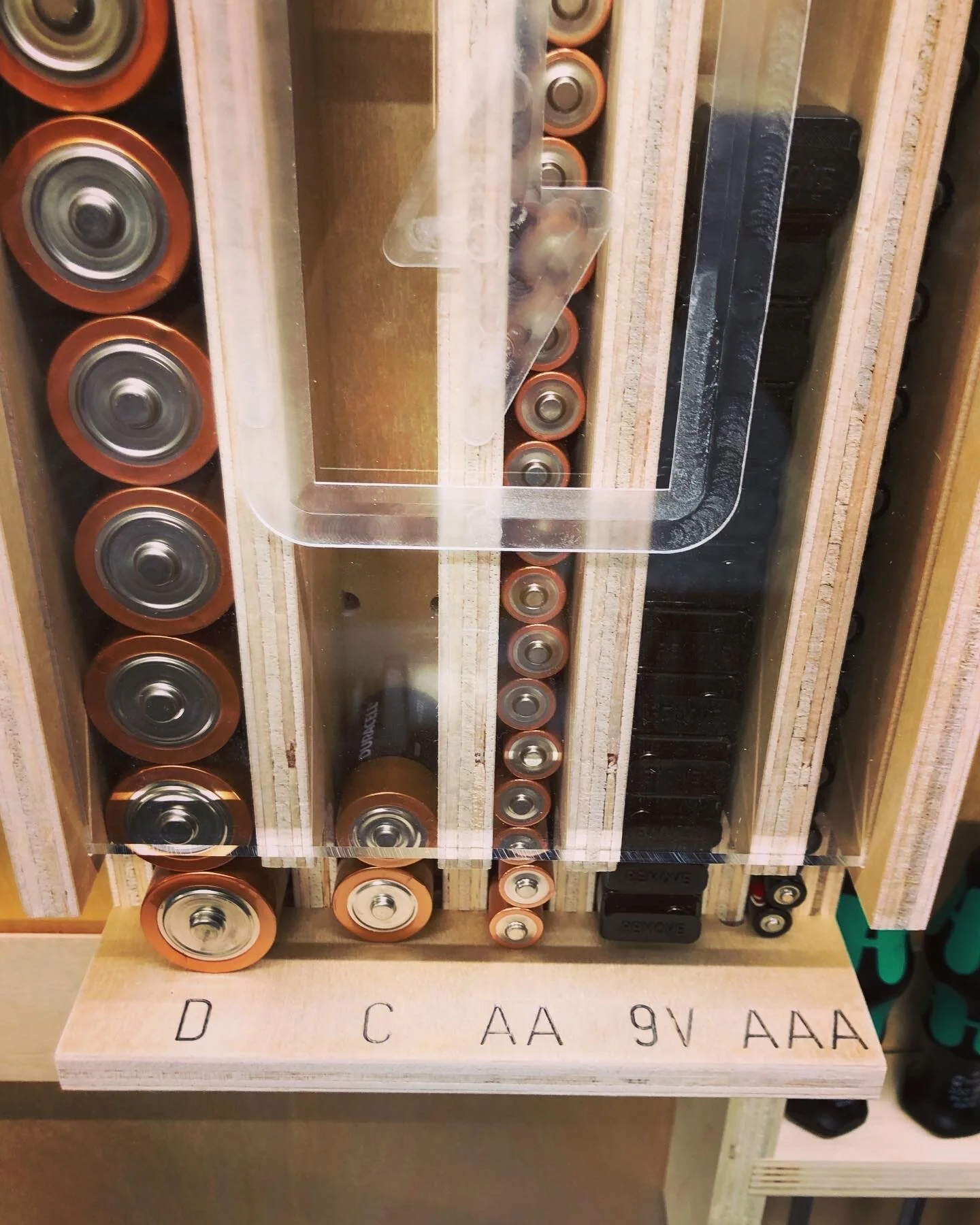
Design, Woodworking Lee Bizek 5/21/20 Design, Woodworking Lee Bizek 5/21/20 Battery Dispenser Designed in Fusion 360 Read More
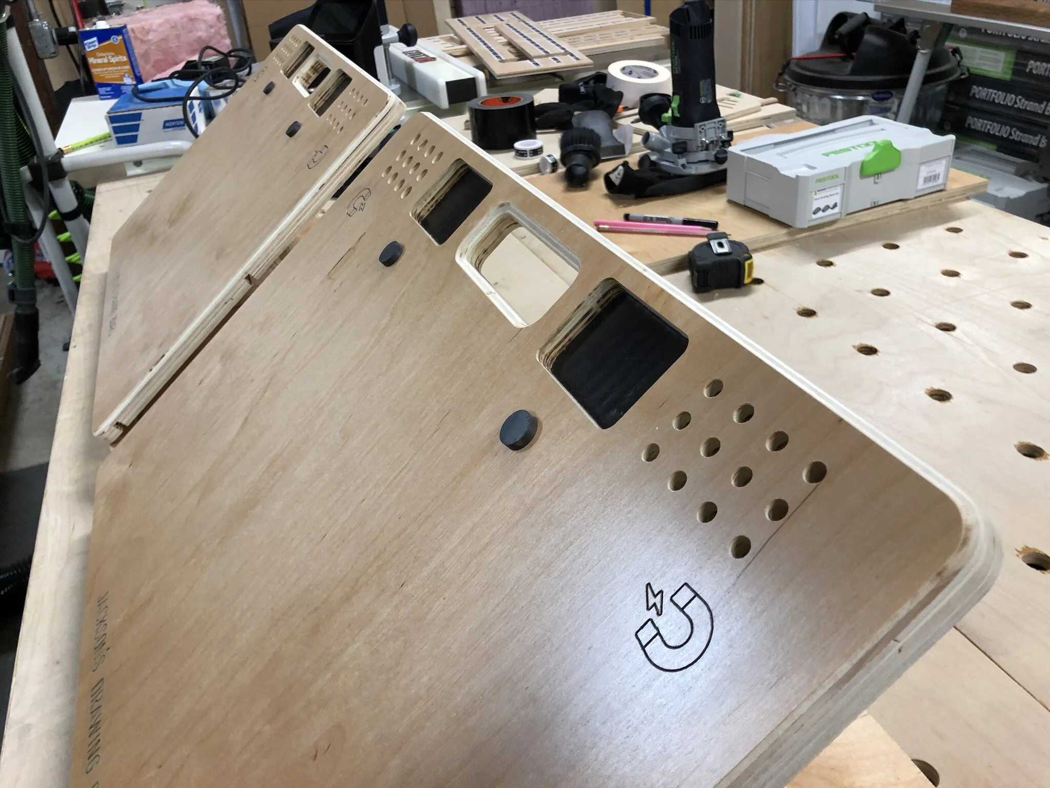
Tools, Design Lee Bizek 12/14/19 Tools, Design Lee Bizek 12/14/19 Corner Jigs made with Shaper Origin Read More
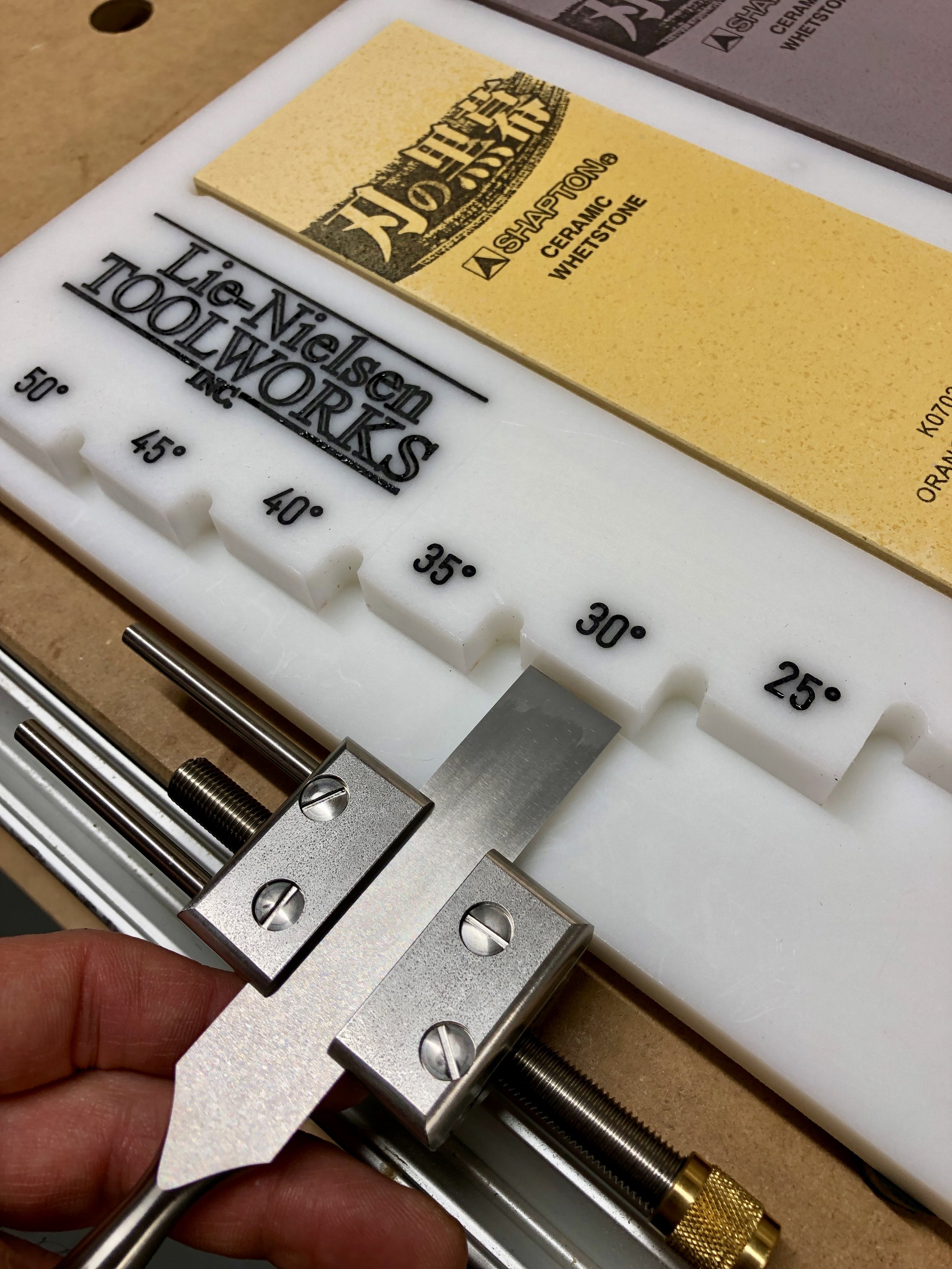
Tools Lee Bizek 11/9/18 Tools Lee Bizek 11/9/18 Horizontal Support for Shaper Origin "Ultimate" Vertical Workstation Read More
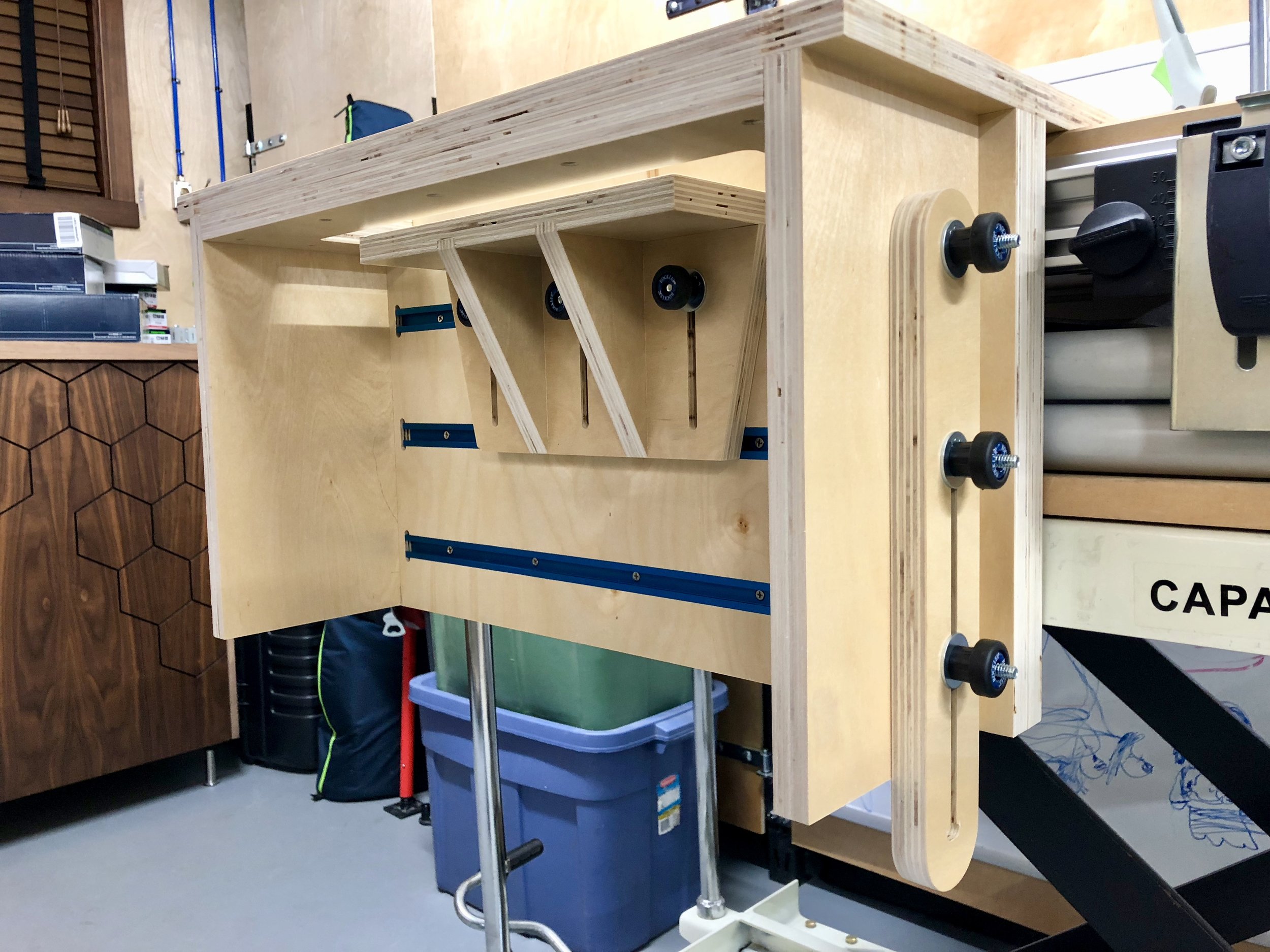
Tools Lee Bizek 7/6/18 Tools Lee Bizek 7/6/18 "Ultimate" Vertical Workstation for Shaper Origin Read More
Tools Lee Bizek 6/25/18 Tools Lee Bizek 6/25/18 Turning a Wood Mallet and Engraving End with Shaper Origin Read More
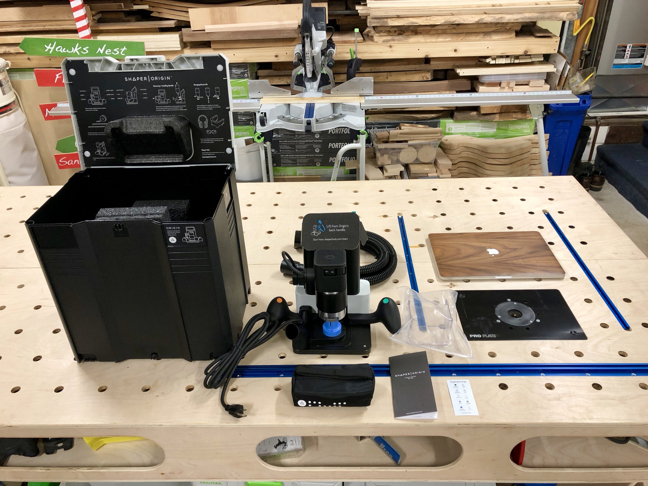
Tools, Innovation Lee Bizek 2/24/18 Tools, Innovation Lee Bizek 2/24/18 My Shaper Origin is finally here!!! Read More